Indie game storeFree gamesFun gamesHorror games
Game developmentAssetsComics
SalesBundles
Jobs
TagsGame Engines

Alcoholics Anonymous

5
Posts
1
Topics
2
Followers
A member registered Jun 24, 2020

Recent community posts

(4 edits)

I ran a 30 minute gaming session on an issue 4 board inside a ZX NEXT case, playing:

Nothing (128K @ 28 MHz)
Galaxy of Errors (ZX NEXT)
Warhawk (ZX NEXT)
Delta's Shadow (ZX NEXT)
The Next War (ZX NEXT)

.xper -dx produced:
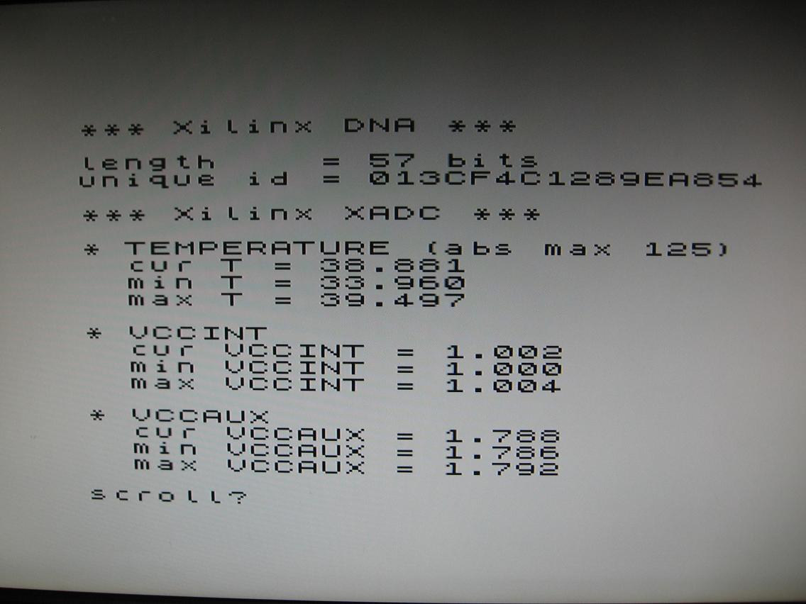
Error in the temperature sensor is +- 4 C and error in the voltage sensor is +-1% (see DS181 Artix 7 data sheet, page 57).

Room temperature was about 26 -27 C last night with the Next reporting initial temperature of 30 C; that would suggest an error of +3 C at least initially.  I think the error I've seen with this fpga is actually smaller than that because we don't get to see the temperature readings accumulated by the anti-brick core which initially runs after power up.  The fpga very quickly warms up to a steady temperature after power on.  So the XADC temp recorded may actually be closer to 26- 27 C while the anti-brick core runs but by the time the ZX NEXT core is booted (which clears accumulated data), the fpga has already warmed up to an idle temperature.

VCCINT is regulated at 1 V and VCCAUX at 1.8 V.  (Not shown) VCCBRAM is regulated at 1 V.

Complete source and xper binary can be downloaded from:

https://1drv.ms/u/s!Ag5xpjL3gA5yk1HghqNPWo2SvgHj?e=Y3Ew8X

THE DOT COMMAND

The last part is deciding on how the dot command should be invoked.  The idea here is to support three options:

-R to reset the XADC

-d to read the DNA

-x to read the XADC temperature and supply voltages

We'll follow standard unix convention by allowing both of these types of invocations:

.xper -R -d -x
.xper -Rdx

If xper is entered on its own, help text should be printed.  If an unknown option is specified, an error should be generated.

For C, we're using Z88DK to compile the program.  It knows about dot commands and how to automatically produce them.  By default, it will properly parse the command line for us into C's standard argc/argv interface and it will arrange to exit properly back to basic, including registering an error intercept in case basic generates an error while the dot command runs.  This happens, for example, if the program printing causes scroll? to appear and the user presses space to break.  This case has to be taken care of for reliable return to basic.

C Programs start at main():

unsigned char old_cpu_speed;
void cleanup(void)
{
   ZXN_NEXTREGA(0x07, old_cpu_speed);          // restore original cpu speed
}
unsigned char board_issue;
int main(unsigned int argc, char **argv)
{
   // speed up
   
   old_cpu_speed = ZXN_READ_REG(0x07) & 0x03;  // remember the current cpu speed
   ZXN_NEXTREG(0x07, 0x03);                    // run at 28 MHz
   
   atexit(cleanup);                            // always run cleanup when program terminates

We're going to run this dot command at 28 MHz (why not?) but we'll restore the cpu speed on exit.  To do that, we store the current cpu speed in a variable and then set the speed to 28 MHz.  A single exit function is registered with atexit().  The startup code guarantees that this function will be run when the program exits no matter what happens.  The cleanup() function registered will restore the proper cpu speed.

Options parsing is straightforward:

   // check options & help
   strupr(argv[0]);                            // capitalize name of dot command
   board_issue = (ZXN_READ_REG(0x0f) & 0x0f) + 2;
   if ((argc == 1) || (board_issue < 4))       // if no options or board issue too low
   {
      printf("\n"
             "%s 1.0\n\n"
             "Read Xilinx Peripherals\n\n"
             "* Xilinx DNA\n\n"
             "-d  reports the fpga unique id\n\n"
             "* Xilinx XADC\n\n"
             "-R  resets the xadc\n"
             "-x  reports status of sensors\n\n"
             ".%s -dx\n\n"
             "running on an issue %u board\n"
             "%s",
             argv[0], argv[0], board_issue,
             (board_issue < 4) ? "ISSUE 4 REQUIRED\n\n" : "\n"
            );
   
      exit(0);
   }
   // parse command line
   
   for (unsigned char i = 1; i < (unsigned char)argc; ++i)
      option_parse(strrstrip(strstrip(argv[i])));   // remove spaces around option (bizarre case)


ESXDOS starts dot commands with the HL register pointing at the string following the dot command name.  NEXTZXOS does that as well for compatibility but it also passes the whole dot command line string, beginning with the dot command name, in BC.  Z88DK uses the latter for command line parsing so that argv[0] will contain the dot command name as is normal for command line invocations in unix.

The command line parsing puts the number of words in argc.  There is always at least one word (the dot command name).  Words are space separated text in the command line string.  Quotes can be used to group together text that contains spaces.  The array argv[] contains pointers to each word on the command line.  argv[0] is always the dot command name.

The board issue is read from the new nextreg 0x0F and if the program is not running on an issue 4 board or if the dot command is started without any arguments then the help text is printed.  The help text uses argv[0] for the dot command name so it is possible to rename the dot command and still have the help text print properly.

The code for parsing the command line is in a separate file "options.c".  The main code simply goes through each word, one at a time and passes a pointer to the word to the option_parse() function.  The word might be modified by removing leading and trailing whitespace.  We're protecting against wise guys who might invoke with quoted options as in .xper "  -Rdx  ".  Because it's quoted, Z88DK will include those spaces in the first word it parses.

struct flag
{
   unsigned char xdna;
   unsigned char xadc_reset;
   unsigned char xadc;
};
struct flag flags = { 0, 0, 0 };
void option_parse(unsigned char *s)
{
   if (*s == '-')
   {
      while (*++s)
      {
         switch (*s)
         {
            case 'd':
               flags.xdna = 1;
               break;
            
            case 'R':
            case 'r':
               flags.xadc_reset = 1;
               break;
            
            case 'x':
               flags.xadc = 1;
               break;
            default:
               exit(ESX_ENONSENSE);            
         }
      }
      
      return;
   }
   exit(ESX_ENONSENSE);
}

A single byte flag for each of -R, -d, -x is created and initialized with 0 (false).  option_parse() examines each word it is passed from the main program and sets the flags appropriately.  If there's no leading - or the option is not recognized then a canned error is generated via exit().  Returning a 0 value indicates success to NextBASIC and non-zero indicates an error.  ESX_NONSENSE is a canned error message provided by NextZXOS.

Back to main, the last part is calling the implementation functions for each option selected:

   // actions
   
   if (flags.xdna)
   {
      read_xilinx_dna();
   
      printf("\n"
             "*** Xilinx DNA ***\n\n"
             "length    = %u bits\n"
             "unique id = %016llX\n",
             xdna_len, xdna
            );
   }
   
   if (flags.xadc_reset)
   {
      printf("\nXADC RESET\n");
      reset_xilinx_xadc();
      z80_delay_ms(100*8);   // some time for new data to be collected (*8 for 28 MHz)
   }
   
   if (flags.xadc)
   {
      printf("\n*** Xilinx XADC ***\n");
      read_xilinx_xadc();
   }
   
   printf("\n");
   return 0;
}

This is all very straightforward and 0 is returned to indicate success.

COMPILING USING Z88DK

It's all done in one line for this project since it's so simple.

The pragmas controlling the compile are placed at the top of the main xper.c file:

#pragma printf = "%s %f %llX %u"
#pragma output CLIB_EXIT_STACK_SIZE = 1

The size of printf is controlled by only including the converters used in the program.  It's doubly necessary because float code and 64-bit integer code is not included by default.

The exit stack size is set to 1, meaning only one function can be registerd with atexit().  This saves a few bytes in the atexit() table of functions.

The compile line comes down to this:

zcc +zxn -v -startup=30 -clib=sdcc_iy -SO3--max-allocs-per-node200000 --opt-code-size xper.c option.c -o xper -lm -subtype=dot -Cz"--clean" -create-app

+zxn : choose zx next target

-v : be verbose in reporting on steps taken in the compile process

-startup=30 : use rst 16 for printing (stdout) and input is unconnected (stdin)

-clib=sdcc_iy : use zsdcc as c compiler

-SO3 : use aggressive peephole optimization

--max-allocs-per-node200000 : high depth for zsdcc code optimizer

--opt-code-size : use rules that reduce code size, especially for 32-bit and above integers

xper.c option.c : the list of files to compile

-o xper : the root name of output files

-lm : link the math48 floating point library code (40-bit mantissa, 8-bit exponent)

-subtype=dot : the type of compile

-Cz"--clean" : tell appmake to erase intermediate files it uses in forming the output binary

-create-app : invoke appmake to automatically build the output file (in this case a dot command)

The output file will be "XPER" without any extension.  This can be placed in the /dot directory and invoked with ".xper" from basic or the command line.  If you save it as "XPER.DOT" you can invoke it from another directory with syntax like this:  "../xper.dot".  The first dot introduces the dot command; what follows must be a path to the dot command, in this case "./xper.dot" (./ means the current directory).  Having the DOT extension also means the program can be launched by the browser.  However the browser will launch it without arguments which produces the useless help text.  A dot command intended to be invoked by the browser should be written to do something useful when no arguments are given.

EXAMPLE RUN

Let's save that for the next post with a screenshot showing how hot the fpga gets after a gaming session.

(2 edits)

Source package and binary : https://1drv.ms/u/s!Ag5xpjL3gA5yk1HghqNPWo2SvgHj?e=Y3Ew8X

XPER - An issue 4 xilinx peripherals dot command

There are at least two reasons this dot command would be disqualified.  One is I wrote it a couple of days before dotjam started for testing purposes and the other is it's only for issue 4 boards which means there are only four people in the world right now who could run it :)

I thought I would share it anyway as an exhibition entry to learn something about the issue 4 boards for KS2 that is different from KS1 and so that people can see an example of writing a dot command in C.  I have plans for a couple more, one of which might qualify for the dotjam, but I don't know if I will have time to do them before the deadline.  We'll see.

So you thought the KS1 and KS2 ZX Nexts would be equivalent?  Well they are -- the same hardware is implemented on both and software runs on both versions identically.  But a few facilities offered by the Artix 7 are being exposed on the new boards.  Here they are:

(1) The Artix 7 has extra pins available whereas the Spartan 6 has all its i/o already committed.  This allowed us to add optional hardware flow control for the esp module through two additional pins (cts and rts).  There is a plan to do the same for the Spartan 6 boards re-using the two esp gpio pins already routed to that fpga.  This dot command has nothing to do with the esp.

(2) Both the Artix 7 and the Spartan 6 have a "DNA" built into them.  This is a 57-bit string that uniquely identifies the fpga.  It can be used to identify a specific ZX NEXT computer.  I do not recommend using it for software copy protection because it would take about 5 minutes for someone to modify the open source ZX NEXT hardware implementation to fake any id desired.  However, it cannot be faked for fpga cores and there may be a need for that if alternate cores have to be licensed in some way to individual users.

The Spartan 6 DNA string is not attached in current cores but the Artix 7 implementation does have it implemented.  This dot program will be able to read that unique DNA string.

(3) The Artix 7 has two 12-bit analog to digital converters built in.  The KS2 pcb has exposed vias for three channels for DIY projects but otherwise makes no use of the facility.  Internally, the XADC can measure fpga temperature and supply voltages.  This dot command will be reading the XADC to report the temperature and supply voltages.

NEXTREG

Starting in version 3.02.00 of the core, there will be some new nextreg to support the above:

0x0F (15) => Board ID
(R)
  bits 7:4 = Reserved, 0
  bits 3:0 = Board ID
    0000 = ZXN Issue 2, XC6SLX16-2FTG256, 128Mbit W25Q128JV, 24bit spi, 64K*8 core size
    0001 = ZXN Issue 3, XC6SLX16-2FTG256, 128Mbit W25Q128JV, 24bit spi, 64K*8 core size
    0010 = ZXN Issue 4, XC7A15T-1CSG324, 256Mbit MX25L25645G, 32bit spi, 64K*34 core size

This nextreg identifies which board version you have.  Issue 2 are KS1 Nexts and the NGO.  Issue 3 is the last (unreleased) Spartan 6 board made during KS2.  Issue 4 is the Artix 7 board that will be used for KS2 machines.

0xF0 (240) => XDEV CMD
(R/W Issue 4 Only) (soft reset = 0x80)
   * Select Mode
     (R)
       bit 7 = 1 if in select mode
       bits 1:0 indicate currently selected device
         00 = none
         01 = Xilinx DNA
         10 = Xilinx XADC
     (W)
       bit 7 = 1 to enter select mode, 0 to enter selected device mode (no other bits have effect)
       bit 6 = 1 to change selected device
       bits 1:0 selected device
         00 = none
         01 = Xilinx DNA
         10 = Xilinx XADC
   * Xilinx DNA Mode
     (R)
       bit 0 = dna bit (serial stream shifts left)
       the first eight bits read will indicate the length of the following dna bits
     (W)
       bit 7 = 1 to enter select mode (write has no other effect)
       otherwise causes dna string to reload, ready for fresh read
   * Xilinx XADC Mode (Documented in Xilinx Series 7 UG480)
     (R)
       bit 6 = 1 if XADC is busy with conversion (BUSY)
       bit 1 = 1 if XADC conversion completed since last read (EOC, read clears)
       bit 0 = 1 if XADC conversion sequence completed since last read (EOS, read clears)
     (W)
       bit 7 = 1 to enter select mode (write has no other effect)
       bit 6 = 1 to reset XADC (RESET)
       bit 0 = 1 to start conversion (CONVST)
* Re-enter select mode at any time by writing to the register with bit 7 set
* Select a device to communicate with by writing to the register with bits 6 & 7 set
* Exit select mode by writing zero to bit 7; thereafter the particular device is attached to the nextreg
Xilinx peripherals are selected and read/written through this single nextreg.  For the Artix 7, the DNA and XADC are made accessible.
0xF8 (248) => XADC REG
(R/W Issue 4 Only) (hard reset = 0)
   bit 7 = 1 to write to XADC DRP port, 0 to read from XADC DRP port **
   bits 6:0 = XADC DRP register address DADDR
* An XADC register read or write is initiated by writing to this register
* There must be at least six 28 MHz cycles after each r/w to this register
** Reads as 0
0xF9 (249) => XADC D0
(R/W Issue 4 Only) (hard reset = 0)
   bits 7:0 = LSB data connected to XADC DRP data bus D7:0
* DRP reads store result here, DRP writes take value from here
0xFA (250) => XADC D1
(R/W Issue 4 Only) (hard reset = 0)
   bits 7:0 = MSB data connected to XADC DRP data bus D15:8
DRP reads store result here, DRP writes take value from here

Nextreg 0xF0 is a common interface to all Xilinx peripherals (all two of them right now).

In addition, the analog to digital converter (XADC) is programmable through a separate DRP port that has a 16-bit wide data bus.  A register is selected in nextreg 0xF8 along with a read or write operation specified in bit 7.  Data is read/written via nextreg 0xF9 and 0xFA.

The Xilinx XADC is described in UG480 ( https://docs.xilinx.com/v/u/en-US/ug480_7Series_XADC ).

READING THE ARTIX 7 DNA STRING

The Artix 7 dna string is 57 bits long and is read serially, one bit at a time.  This is connected through nextreg 0xF0 as described above.

The procedure is to first select the DNA peripheral, then put nextreg 0xF0 into peripheral mode (rather than select mode), reset the DNA module so it goes back to its first bit and then read out the dna string one bit at a time.  After each bit read, the DNA automatically shifts to the next bit.

The C code that does this is the following:

uint8_t xdna_len;
uint64_t xdna;
void read_xilinx_dna(void)
{
   ZXN_NEXTREG(0xf0, 0xc1);  // select xilinx dna
   ZXN_NEXTREG(0xf0, 0);     // enter xilinx dna mode
   ZXN_NEXTREG(0xf0, 0);     // reload dna registers
   
   xdna_len = 0;
   
   for (unsigned char i = 0; i != 8; ++i)
      xdna_len = (xdna_len << 1) + ZXN_READ_REG(0xf0);
   
   xdna = 0;
   
   for (unsigned char i = xdna_len; i; --i)
      xdna = (xdna << 1) + ZXN_READ_REG(0xf0);
   
   ZXN_NEXTREG(0xf0, 0xc0);  // back to select mode
}

The first eight bits read is the dna string length.  For both the Spartan 6 and Artix 7, this is a 57-bit string but it could be different if another fpga is used so the length has been made part of the string.

As can be seen from the code, the DNA bit is read from the LSB of nextreg 0xf0 with the rest of the bits zero.  This allows the string to be read by left shifting the current result and adding in the nextreg read.

The following 57-bit string is read into a 64-bit unsigned integer.  In C we're being careful to specify the integer size by declaring it "uint64_t".

Once the dna is read, nextreg 0xf0 is placed back into peripheral select mode.

READING THE ARTIX 7 XADC

The Artix 7 is going to be constantly measuring the internal temperature and the supply voltages.  It also keeps track of minimum and maximum values since (xadc) reset.  An xadc reset corresponds to a ZX NEXT hard reset or a reset command sent to the XADC.

The XADC is described in Xilinx's UG480 (link above) and the register list can be found on page 37.  We are interested in xadc status registers 0x00, 0x01, 0x02, 0x06, 0x20, 0x21, 0x22, 0x23, 0x24, 0x25, 0x26 and 0x27.  For DIY projects the VP/VN, VAUXP/N 8 and VAUXP/N 15 channels are connected to vias on the pcb.

The value read from these registers is 16-bits wide but only the top 12-bits are significant.  This returns a value between 0 and 4095.

A conversion of this value to temperature in degrees celsius is done using this formula:

T = VALUE * 503.975 / 4096 - 273.15  (UG480 page 33)

For supply voltage measurements the conversion to voltage follows this formula:

V = VALUE / 4096 * 3  (UG480 page 34)

In C these two conversions are implemented as separate functions:

float xadc_temp(uint16_t t)
{
   // UG480 page 33
   return ((t * 503.975) / 4096.0) - 273.15;
}
float xadc_volt(uint16_t v)
{
   // UG480 page 34
   return (v / 4096.0) * 3.0;
}

I used a data driven approach to read all the measured values, perform the conversions and print results.

Each entry in the XADC struct contains string to print, xadc register to read (address), storage location to hold read result and a conversion function to use for the result.  If the conversion function is NULL (0) then the entry is understood to be a heading in the name string only.

struct XADC
{
   unsigned char *name;
   uint8_t address;           // XADC read address
   uint16_t value;            // filled in when XADC read
   float (*conv)(uint16_t);   // 0 = no measurement
};
struct XADC xadc[] = {
   { "\n* TEMPERATURE (abs max 125)", 0, 0, 0 },
   { "  cur T = ", 0, 0, xadc_temp },
   { "  min T = ", 0x24, 0, xadc_temp },
   { "  max T = ", 0x20, 0, xadc_temp },
   { "\n* VCCINT", 0, 0, 0 },
   { "  cur VCCINT = ", 0x01, 0, xadc_volt },
   { "  min VCCINT = ", 0x25, 0, xadc_volt },
   { "  max VCCINT = ", 0x21, 0, xadc_volt },
   { "\n* VCCAUX", 0, 0, 0 },
   { "  cur VCCAUX = ", 0x02, 0, xadc_volt },
   { "  min VCCAUX = ", 0x26, 0, xadc_volt },
   { "  max VCCAUX = ", 0x22, 0, xadc_volt },
   { "\n* VCCBRAM", 0, 0, 0 }, 
   { "  cur VCCBRAM = ", 0x06, 0, xadc_volt },
   { "  min VCCBRAM = ", 0x27, 0, xadc_volt },
   { "  max VCCBRAM = ", 0x23, 0, xadc_volt }
};

The function that simultaneously reads the XADC and prints results is then straightforward:

void read_xilinx_xadc(void)
{
   for (unsigned char i = 0; i != sizeof(xadc) / sizeof(struct XADC); ++i)
   {
      if (xadc[i].conv == 0)
      {
         printf("%s\n", xadc[i].name);
      }
      else
      {
         ZXN_NEXTREGA(0xf8, xadc[i].address);                                                // read XADC register
         xadc[i].value = (uint16_t)((ZXN_READ_REG(0xfa) * 256) + ZXN_READ_REG(0xf9)) / 16;   // ADC result is in top 12 bits
         
         printf("%s%.3f\n", xadc[i].name, xadc[i].conv(xadc[i].value));
      }
   }
}

The FOR loop goes through each entry in the struct in turn and finds out if the entry is a heading or not, taking appropriate action.

The dedicated DRP interface to the XADC is used in nextreg 0xF8, 0xF9, 0xFA to read the XADC registers.  Since the xadc addresses stored in the struct have bit 7 reset (are < 128), writing to the nextreg initiates a read operation with results available in nextreg 0xF9 and 0xFA within 7 cycles at 28 MHz.  Since I/O on the Z80 is 16 cycles, the results are available to read in the instruction following the 0xF8 nextreg write.

The printf uses %.3f specifier which means print the float with three decimal place precision.

RESETTING THE ARTIX 7 XADC

The reset happens in two parts.  In the first part, the XADC is reprogrammed to the default state by writing appropriate values to registers 0x40 through 0x5c.  These are mostly 0 values which you can refer to in the UG480 document.  After this reset, the XADC will return to reading the internal temperature and supply voltages only.  A reset pulse has to be sent to the XADC following this register initialization and this is done through the nextreg 0xf0 peripherals interface.

The list of XADC programming values is held in a simple struct:

struct XADC_RESET
{
   unsigned char reg;
   uint16_t val;
};
struct XADC_RESET xadc_reset[] = {
   { 0x40, 0x0000 },   // Config Reg 0
   { 0x41, 0x00f0 },   // Config Reg 1
   { 0x42, 0x0000 },   // Config Reg 2
   
   { 0x48, 0x0000 },   // Sequencer Channel Selection (on-chip)
   { 0x49, 0x0000 },   // Sequencer Channel Selection (aux)
   { 0x4a, 0x0000 },   // Measurement Averaging (on-chip)
   { 0x4b, 0x0000 },   // Measurement Averaging (aux)
   { 0x4c, 0x0000 },   // Analog Input Mode (on-chip)
   { 0x4d, 0x0000 },   // Analog Input Mode (aux)
   { 0x4e, 0x0000 },   // Settling Time (on-chip)
   { 0x4f, 0x0000 },   // Settling Time (aux)
   
   { 0x50, 0x0000 },   // Upper Temperature Alarm
   { 0x51, 0x0000 },   // Upper VCCINT Alarm
   { 0x52, 0x0000 },   // Upper VCCAUX Alarm
   { 0x53, 0x0000 },   // OT Alarm Limit
   { 0x54, 0x0000 },   // Lower Temperature Alarm Reset
   { 0x55, 0x0000 },   // Lower VCCINT Alarm
   { 0x56, 0x0000 },   // Lower VCCAUX Alarm
   { 0x57, 0x0000 },   // OT Alarm Reset
   { 0x58, 0x0000 },   // Upper VCCBRAM Alarm
   { 0x5c, 0x0000 }    // Lower VCCBRAM Alarm
};

The reset function first performs these register writes through the DRP interface on nextreg 0xF8, 0xF9 and 0xFA as before.  This time we are writing so the value to write has to be written first to nextreg 0xF9, 0xFA and then the write initiated by writing the register address to nextreg 0xF8 with bit 7 set.

void reset_xilinx_xadc(void)
{
   // re-write all configuration registers
   for (unsigned char i = 0; i != sizeof(xadc_reset) / sizeof(struct XADC_RESET); ++i)
   {
      ZXN_NEXTREGA(0xf9, xadc_reset[i].val & 0xff);   // LSW of register value
      ZXN_NEXTREGA(0xfa, xadc_reset[i].val >> 8);     // MSW of register value
      ZXN_NEXTREGA(0xf8, xadc_reset[i].reg + 0x80);   // write register
   }
   // reset clears accumulated sensor data and restarts adc
   
   ZXN_NEXTREG(0xf0, 0xc2);   // select xilinx xadc
   ZXN_NEXTREG(0xf0, 0);      // enter xilinx xadc mode
   ZXN_NEXTREG(0xf0, 0x40);   // xadc reset
   ZXN_NEXTREG(0xf0, 0xc0);   // back to select mode
}

After the configuration is done, the XADC is reset through the peripherals interface on nextreg 0xF0.  This connects to more signals on the XADC module that are not available through the DRP.  The reset bit is what we are interested in.

First the XADC is selected in nextreg 0xf0, then the peripheral mode is entered by writing 0.  After this we are connected to the XADC pins.  Writing 0x40 pulses the reset signal.  Then nextreg 0xf0 is returned to select mode.


... continued in the next post

About the interrupt triggering.  Devices that are not im2 aware should not drive any value on the data bus during an intack cycle.  Instead they should rely on the expansion bus pullups to ensure a 0xff value is read.  Doing otherwise would be incompatible with devices that are im2 aware.  The zx next will be an im2 aware computer and there are original spectrum peripherals that operated in the im2 mode, eg the amx mouse.  In general, any device using standard zilog peripheral ics can be im2 enabled.

Email contact through zxdesign.info doesn't seem to have worked so I will try here.  

We'd like to add an eight channel ctc to the zx spectrum next using ports 0x183B through 0x1F3B.  There are no conflicts currently according to the page as it is today and I've spoken to Jan (mb03) about it already.   I think he's the only other developer actively creating new hardware at the moment.

So I'll go ahead with this unless I hear otherwise.