Hi Joe,
Here's a writeup about using PixelCNC to generate toolpaths for making an inlay that I sent to another user a few months ago. Let me know if you have any questions or need help with anything :]
Here are the two project files for the ladybug inlay that the writeup refers to:
2x2x0.15_Ladybug_Inlay_Female.pnc
2x2x0.15_Ladybug_Inlay_Male.pnc
With the two project files the final cutting depth for both is 0.1 inches because this is a relatively small inlay. For a larger inlay you will probably want to go a bit deeper but I suggest starting with small inlays and working your way up because machine squareness and flex will throw cuts off and result in your inlays not fitting as well. For most inlays you can get away with a pretty small overall maximum cutting depth, there's not a lot of reasons to go deeper than is necessary - and there's less cutting with a shallower inlay, which is a good thing with hardwoods like walnut/maple.
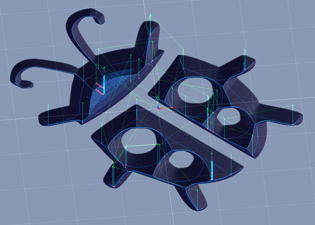
Starting with the the female side's project file we are doing a pretty basic V-carving using the Medial-Axis carving operation (found under Specialty Cuts on the Operation Type dialog when creating a new operation) which can be used to cut designs with V-bits, tapered ballnose cutters, and ballnose cutters (aka 'B-Carving'). This operation type generates cuts which follow the medial-axis of a 2D contour - either from a vector paths-layer, or waterline contoured from the canvas heightmap at a specified Z height, and the tool is moved up/down along the medial-axis so that it's filling the width of the shape.
However, the diameter of the cutter determines the deepest that we can go for a V-carving. More importantly, if a shape/design is too large for our cutter's diameter, then we end up with a medial-axis cut like this where all the areas marked red are left behind as all the cutter can do is hug the perimeter once it is half its diameter from the input contour:
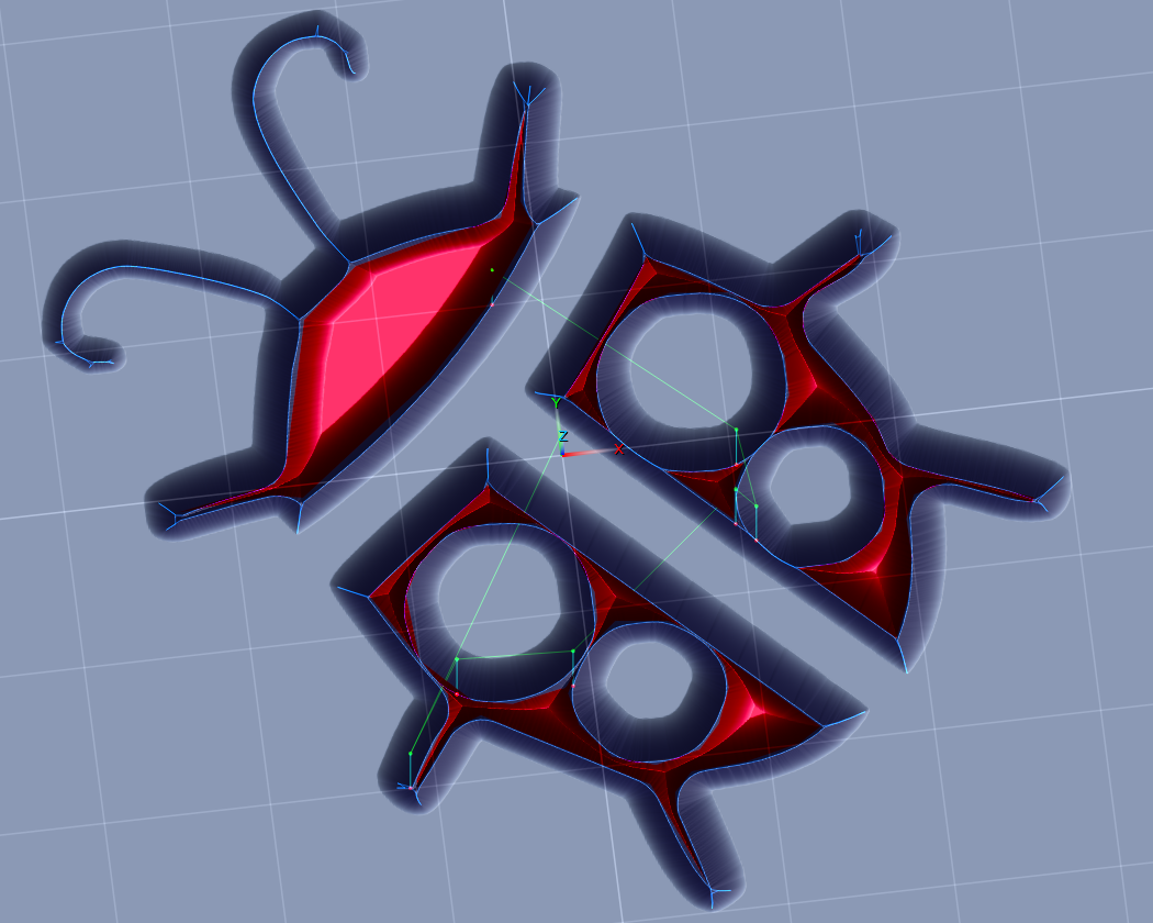
With the female only cutting 0.1" deep with a 90deg v-bit, anything that's farther than 0.05" from the design's edges will need to be removed somehow. This is why we are also including a 2D Profile Milling operation beforehand to clear out the inner areas that the V-carving won't reach by itself, unless we cut deeper (if the bit's diameter and flute length can handle it), or use a wider-angle bit - which would not be ideal for an inlay as small features would come out very thin. You'll want to use a bit with a tip angle of 90 degrees or less.
We are using a paths-layer of the vector design we want to make an inlay out of, which we can directly use as contour input for both of these operation types to generate cutpaths from. This is all covered in the interactive tutorials that come with PixelCNC.
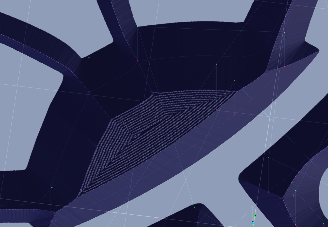
Using a V-bit to mill out the inner areas will leave tiny ridges, depending on our cut stepover, but we only need these ridges to be smaller than the headroom gap that we'll have with our male plug. In the example female project we have the cut stepover for the v-milling set to 0.005" which is a bit smaller than we actually need but on my flimsier machine this also means that my V-carving will be more accurate as the cutter won't be hogging out as much material, resulting in the cuts being more accurate when the V-carving comes through.
We could also use a different bit with a larger stepover, such as a tapered ballnose cutter, and use a larger stepover - but the larger the cutter and stepover the more likely we might end up with spots that are missed, like this situation where a 0.125" flat endmill was used to clear the area inside a V-carved area:
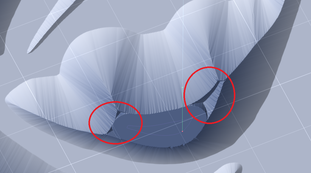
By using the 2D Profile Milling operation with a V-bit we can get in tight spots and remove these unwanted bits that will cause problems with an inlay. Here are the parameters the v-milling operation is using in the female side:
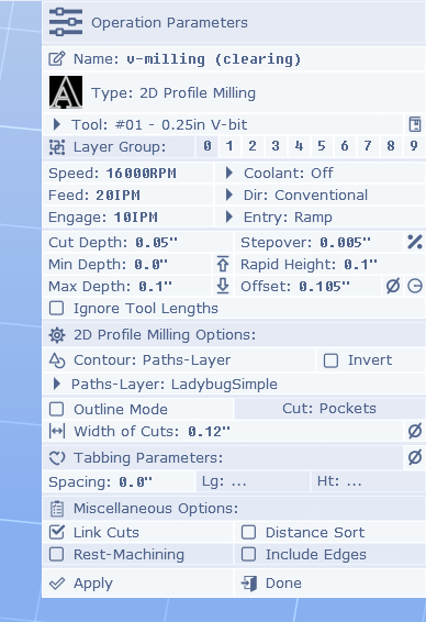
You will want to adjust the speeds/feeds for your machine, and the wood you're using, and for the cut depth and stepover being used. These are parameters you'll have to find out for yourself on your machine through trial-and-error, and suggestions and advice from other people using the same machine as you on the materials you want to cut.
In terms of an inlay, the important parameters here are the Offset and the Width of Cuts. We are cutting 0.1" deep so we want to push our 2D Profiling away from the sides of our design by 0.1", but we add 0.005" on there for the subsequent V-carving operation to come through and clean up.
The Width of Cuts parameter triggers the operation to generate multiple neighboring cuts, similar to the 2D and 2.5D Offset Milling operations, but if we had a larger area to clear we would only need this to go out far enough that it reaches where a flat endmill would come and clear the rest out - enough to get those little bits that are circled in the image above. For this project we're just using the V-bit to clear the whole area out instead.
Here's an example of a V-carving project where the V-bit was also used with a profile milling operation with a Width of Cuts to get the tight spots in the cow's head, and then a flat endmill was used to clear everything else with a pocket roughing, a pocket finishing, and a profile finishing:
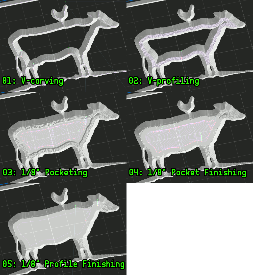
For the female side we won't be going in with a flat endmill to clear the middle, and just use the V-bit and Width of Cuts parameter to fill it with concentric offset cutpaths.
You may also notice that the Entry cut is set to Ramp, this isn't 100% necessary, just something I do to prevent a jarring force on my boingy machine!
So that's the female project, it's really just your basic V-carving but it's important that it's square in all three axes, and the machine isn't flexing and letting the cutter deviate!

The first thing you'll see is that we've mirrored the paths-layer that we're using as contour input for generating our cutpaths. This is accomplished by enabling the Mirror X option on the paths-layer's properties in the Project Canvas mode.
With the male side we have offset the toolpath by 0.025 inches so that the top surfaces of the male don't bottom out on the female side. With a 90 degree V-bit this means that this offset amount will produce an equivalent 0.025" gap between the top of our male plug and the bottom of the female side - and between the top surface of our female side and bottom of our male side (because they're both cut 0.1" deep so an offset shifts the male out of the female). This means we'll have 0.075" where the male's surfaces are interfacing with the female's. For a larger inlay you will want to have a deeper cut, such as 0.15" or 0.2". If we were using a 60 degree V-bit then the headroom would be double what our male offset is, and we'd have 0.05" of "headroom". We could use a smaller offset with a narrower bit.
Here are the parameters for the second profile milling operation, which is the important one that we care about:
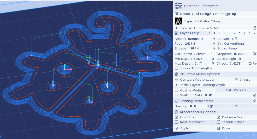
The first two operations are 2D Profile Milling operations using our X-mirrored paths-layer as contour input (shown in orange above), and we have Invert enabled so that we are cutting outside of our paths-layer's paths instead inside. Theoretically, if you could ensure that the bottom of all female cuts are perfectly flat, and the bottom of all male cuts are perfectly flat, then you could just cut the profile of the shape with a V-bit matching the V-bit used for the female, then remove everything outside of that, and make an inlay with two exactly fitting male/female pieces - with no headroom gap whatsoever. Being that we want a little room for our cuts to not be 100% perfect and not consume days of cutting time, we want to have a gap between the top of the male and bottom of the female (and vice-versa).
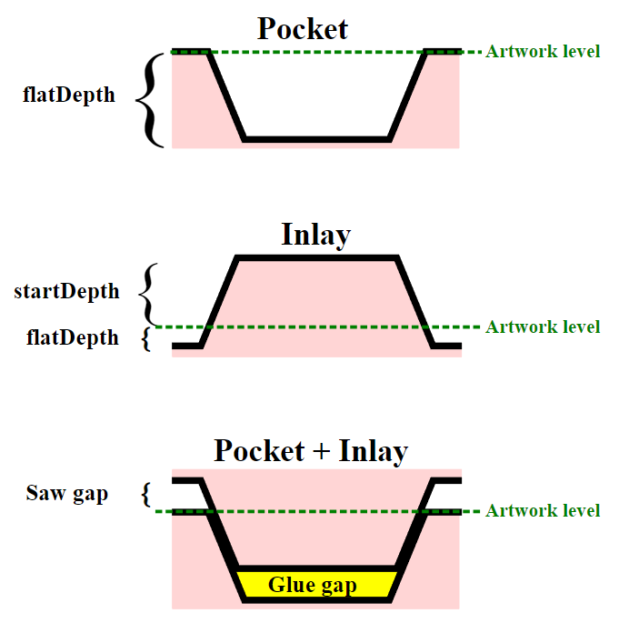
This image I borrowed from KrabCAM's page perfectly shows what we're trying to do:
The first two profiling operations are virtually identical, except that the first one only cuts 75% of the way down, with a larger stepover, and faster feed rate. The first operation is just a roughing operation so that the second operation goes more smoothly. We use the Width of Cuts with a value set to roughly the radius of the endmill that will be coming in to remove all the surrounding material around our plug, to get the tight nooks and crannies where it won't.
The important parameters for our V-profiling operation are the cut Stepover so we don't leave any ridges taller than our headroom gap, the Offset parameter which is equal to the amount of gap we want (for a 90 deg V-bit) plus 0.0025" for our V-carving pass to come through and handle cutting the bottom, which will be the top-surface of the male after it has been glued and has its back milled off, so that we have headroom with the top surface of the female that everything will be mating with.
The situation is that because we're using an Offset on our V-profiling our resulting shape will no longer properly fit as-is into the female side. Inside corners will not be sharp enough to fit corners on the female side. This is where a medial-axis carving operation comes in and handles cutting where we want the top-surface of the female to sit on our male plug.
What is important, especially on a giant spring of a machine like my own, is that the V-profiling cuts go everywhere that the V-carving operation will, to clear material out for it, which can be tricky when there are features close together in a design. This can require preceding the profile milling with a shallower one that also has a smaller Offset, to help clear material out in preparation for the V-carving that follows.
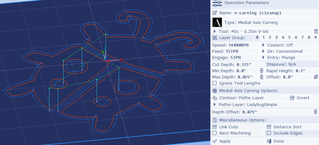
The V-carving operation is only necessary because our V-profiling is offset, which causes inside-corners to puff out and no longer be sharp 0.025" from the bottom (plus we added 0.0025 ontop for the V-carving to cleanup, but even if we didn't the offset would still make it not fit right). So to get that last bit of shaping we need so that it fits properly we are "extending" the male down farther than the design itself, that's what this V-carving operation lets us do:
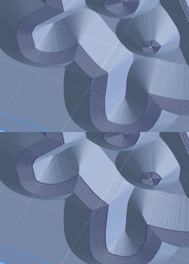
The important parameters here are the Max Depth, which should be equal to the depth of our headroom gap, which is 0.025". This won't work on its own as it will just cut a shallow V-carving in the top surface of the male workpiece which is why the Depth Offset is set to 0.075", which simply moves the generated cuts down to the last 0.025" that we want to extend out of the female - the area called the "saw gap" on the diagram from the KrabCAM site.
Here you can see how the including of the 0.025" V-carving that we've offset down by 0.075" matches our design's orange paths:
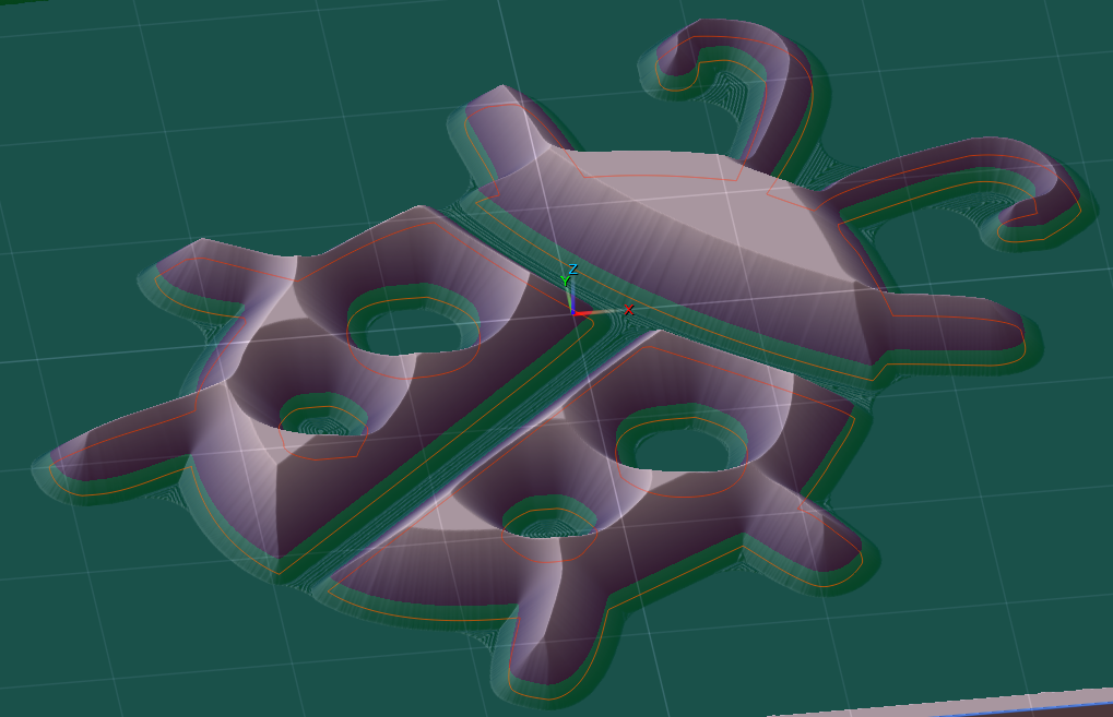
Everything green is what will be outside the female side once they are mated, and everything red will be mating with it and become the inlaid material. You can see that all our V-profiling ridges from before the V-carving operation are well below our gap/headroom, and we could get away with a larger cut stepover - at least on a machine that can handle the forces involved (i.e. not my machine).
What is important is that there is nothing that's not a part of the design that's above this plane, or it will interfere with the female's top-surface and prevent a good fit where all angled cut surfaces are mating.
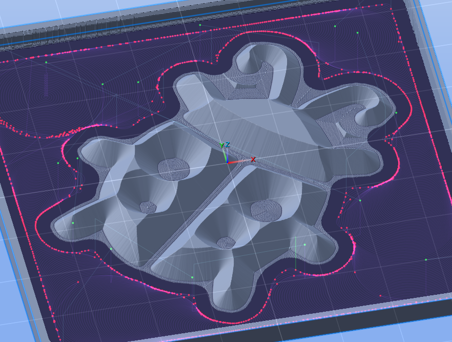
The rest of the male project is just clearing out all the material around the male plug geometry that we want it to have. In the example project file we're using a 2D Trochoidal Milling operation to mill the outside of our paths-layer using a 1/8" endmill (don't forget to enable the Invert option). You can use a 1/4" endmill and really hog it all out, it doesn't have to be perfect - as long as gets any islands of material that weren't reached by the V-profiling operations at the beginning, which you could extend out farther by increasing Width of Cuts, but you'll be adding a good amount of runtime doing that. You'll just want to make sure your clearing toolpath's Offset is large enough to include the 0.025" extension we've created (i.e. half of endmill's diameter + 0.025" + some extra, ~0.005" to 0.015" depending on the project size). Set your Feeds and speeds, Cut Depth, Stepover, and other parameters to whatever your machine can handle when clearing this unwanted material away.
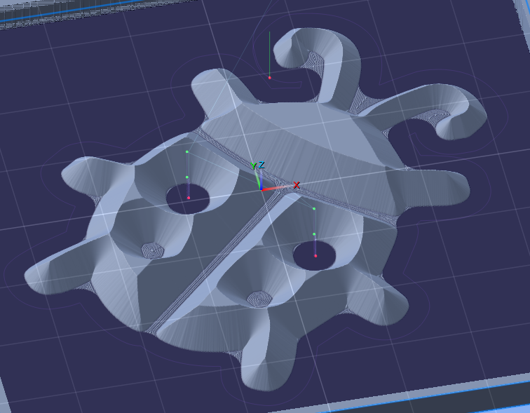
Then the last operation is just a profiling pass with the 1/8" endmill, of course offset by half our cutter's diameter plus our 0.025" gap. You could have a larger Offset and leave some of those V-profiling ridges if you want. What's important is that we get any high spots leftover, like the spots between the front legs and ladybug antennae.
After cutting that you just saw off the sides of the male so you just have the plug geometry, use a liberal amount of glue, and clamp it to the female. You should see a nice even 0.025" gap all around both pieces. Let it sit overnight then come back and saw the back of the male off, or mill it off, etc... Then sand and stain/seal, whatever you want :]
I hope that covers everything. You should be able to learn everything else you need about PixelCNC from the included Interactive Tutorials. After practicing running some G-code from PixelCNC on your machine and becoming comfortable with everything you should then be able to create this ladybug inlay, and then start working up to larger sizes. If your machine is not square you'll find out. Definitely don't jump to a two-foot sized inlay and end up scrapping a bunch of nice wood. Work your way up to it, figuring out what works with your machine and what doesn't.
- Charlie

