Hi Pluto,
Ouch! It tried to move so fast that the machine's own inertia kept it from being able to retract - but you can hear it try with that buzz just before rapiding to the next cut. Glad you were able to solve the puzzle :]
- Charlie
Hi Pluto,
The project file looks fine, the G-code looks fine. It must be something with your CNC controller. After it reaches the XY coordinate at the end of the cut it should then be rapiding up to Z10, which would be 10mm above the workpiece - assuming that Z0 is the top-surface of the workpiece. If you can manually issue commands to your machine, zero the origin somewhere up in the air and then run a G0Z10, and it should move up 10mm. If it doesn't move 10mm upward from the established machine origin, or moves downward, then the controller probably isn't zeroed out where it's supposed to be for the Z axis.
There does appear to be a toolpath artifact that's resulting in many small individual cuts in two spots in your project:
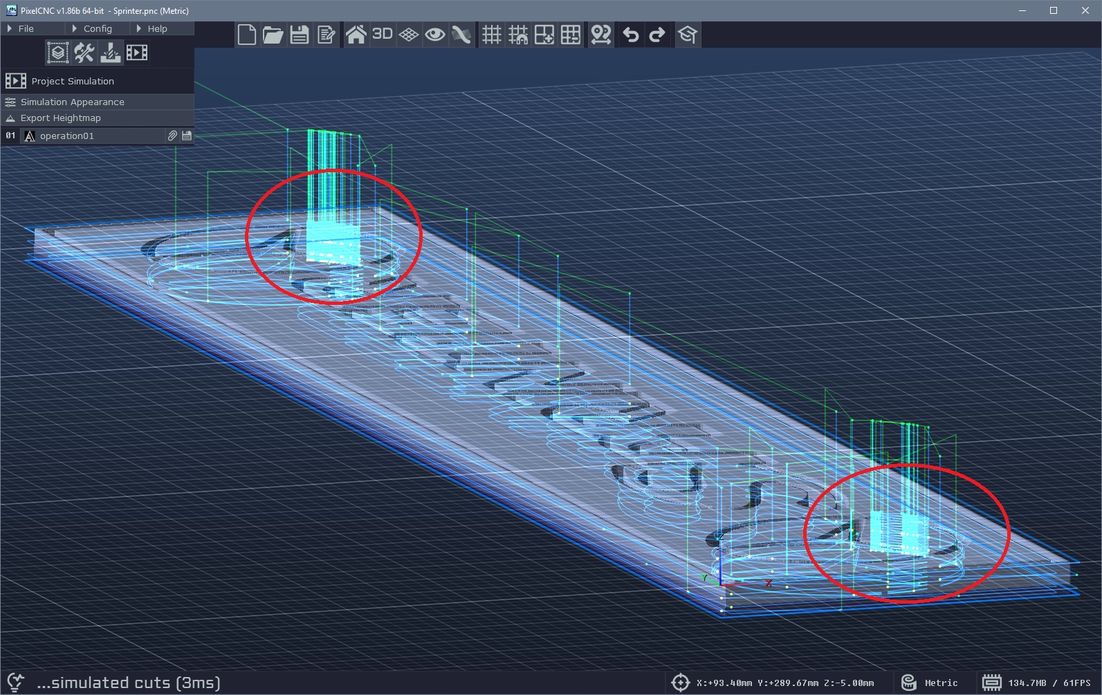
This is caused by a lack of canvas resolution. Increase your Canvas Resolution to 200ppi to get the proper cuts that I imagine you're going for:
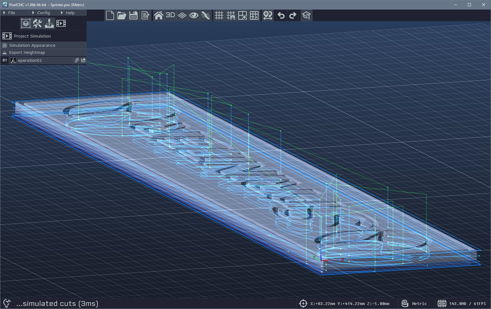
Those cutpaths might've been what caused your cutters to break? Let me know what you find.
- Charlie
Hi Pluto,
The simulation mode only depicts the actual cutpaths being traversed, and not any retractions to the Rapid Height or the rapids themselves. Only ramping and helical entry cuts are also depicted, but plunge entry cuts are not included. It sounds like a potential CNC controller situation, perhaps a work offset that's being triggered. What post-processor are you using?
Have you looked at the G-code output itself to see what's happening at the end of one operation and the beginning of another? I'd like to take a look at it if you could send it over to support@deftware.org :]
- Charlie
Hi Nico,
You can use a flat endmill - with or without a corner radius, or even a ballnose endmill - to perform a roughing pass first using one of the 2.5D milling operations to hog out most of the material first. Then come in with your desired finishing tool with the Parallel Carving operation and its Cut Depth to match its Max Depth so that the toolpath cuts the entirety of the piece in one layer of cuts. This is generally the fastest way to go about a relief carving because you are taking advantage of a larger cutter to remove more material faster. Just be sure to include a non-zero Leave Stock on your roughing operation so that there's some material left for the finishing operation.
You can also use the Parallel Carving operation itself with a larger cutter as a roughing operation, before you come in with your finishing cutter and another parallel toolpath that goes over the whole project in one pass. There is an example project on our Downloads page: https://deftware.org/pages/downloads
Both the Skull Fractal Pattern and Tree of Life projects employ roughing operations before bringing the piece to its final shape with a finishing operation. :]
- Charlie
Hi Nico,
If you are using the Parallel Carving operation with a low Cut Depth relative to your Max Depth then it will be generating multiple layers of cuts that have a lot of "air cutting" as the tool must rapid between cuts. This can be remedied by using the Distance Sort option on the operation's parameters to optimize the order in which the tool traverses cutpaths. Using the Mixed cutting direction and enabling Link Cuts will also greatly reduce the amount of time spent rapiding between cuts when Distance Sort is enabled.
- Charlie
Hi Joe,
For just about everything the geometry of the tool is considered when generating contours and cutpaths for things, including when generating a V-carving toolpath with the Medial-Axis Carving operation. For some of the 2D milling operations it is just treated like any other cutter.
What will probably throw a wrench in things is figuring out how to create the male side of an inlay that will fit properly with a female side that's been cut using a tapered ballnose unless you can somehow truncate the male plug to not bottom-out in the female side, without the plug just being a thin/shallow part that leaves a huge amount of space underneath.
Unless the tapered ballnose cutter's tip radius is narrow enough that it stays at one depth for the entire V-carve operation, you'll end up with the V-carve producing cuts with a radius matching the cutter's, like this:
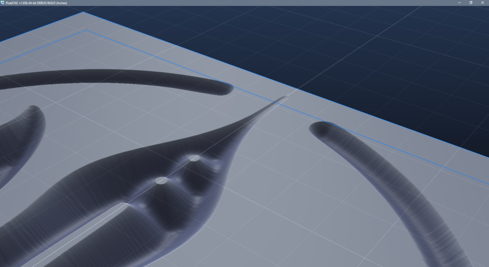
This is made with an exaggerated tapered ballnose to illustrate what I'm referring to. You will want to not have any sharp corners in your design that cause the cutter to cut shallower, resulting in spots that will be difficult to produce matching male geometry for. You'd basically just want the tapered cutter to only perform a profiling cut at a fixed cut depth, rather than a proper V-carve cut where the cutter depth varies with the width of the shape being cut.
Otherwise you'll have to figure out how to make a matching plug like this:
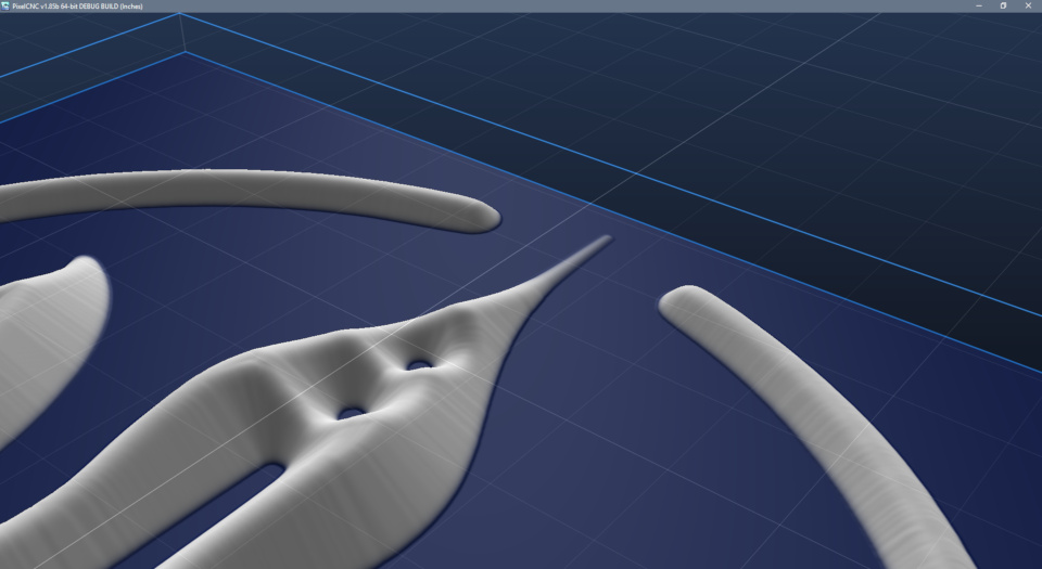
Again, this is an exaggeration that's using a tool with a wide taper angle and a large nose radius, but the issue will still remain with a conventional tapered ballnose if used with the medial-axis carving operation. For any kind of relief carving, or 2.5D milling, a ballnose cutter's geometry is accommodated for though.
Hope that answers your question! :]
- Charlie
Hi Russ,
The main reason I was putting off releasing a proper guide/tutorial for inlays was largely because it will become obsolete once we get the dedicated male-plug inlay operation all dialed in and released, which will replace having separate profiling/V-carving operations. You'll still be able to do things "the old way" but using the new operation will be a bit simpler :]
- Charlie
That's really interesting. There must be somewhere else in PixelCNC's code that is causing it to skip outputting the block if the coolant is set to None, even though the part that actually outputs the coolant block treats None/Off the same :P It will be fixed for the next public release! :]
- Charlie
Hi Joe,
The estimated run times are affected by the acceleration setting under CNC/CAM Settings which you will want to set to your machine's actual acceleration speed to make the run times more accurate :]
Unfortunately there's really no way to 100% accurately determine what the runtime will be for all possible machines in the world simultaneously, one can only hope to get close enough to be useful. It's at least nice to know if something is going to take 30 minutes vs 30 hours!
- Charlie
Hi Joe,
The first option that comes to my mind would be to make multiple separate 2D milling operations that cut at the different depths, and then using a custom modified G-code post specifically for the project file that includes a pause command block between operations. You would need to include the pause command in either the tool change block, one of the the spindle command blocks, or one of the coolant command blocks. It would basically be a bit of a hack where you're just including the pause command inside one of the command blocks that are issued on a per-operation basis. Then with separate operations each cutting a different level, and exporting the G-code using such a custom post as described - with operations combined, you would have the desired result where each cut level would include a stop to let you push a button and tell it to continue.
The second option would be creating each cut depth as a separate option and exporting them as separate G-code files, which would require opening each one to run it for each cut level.
That's the best I can come up with at the moment - but it does give me an idea to include some new functionality in the G-code post-processor format that allows for different commands to occur at different times, such as per-operation, per-toolchange, or every N operations, etc.. I'll have to think about that though and see what I come up with :]
- Charlie
Hi Joe,
Are you talking about just surfacing a regular rectangular area flat? In that case you can just create a project and a Parallel Carving operation with the cutting direction set to Mixed (or if you specifically want Conventional/Climb you can do that too) and just let it generate a toolpath that fills the entire canvas. Then it's just a matter of designating the dimensions of the canvas. You also can set the Canvas Resolution pretty low too as there's no height information that it needs to worry about contouring.
- Charlie
That's pretty good for pine. Those thin areas at the inside-corners definitely aren't gonna hold up though unless maybe it's embalmed with epoxy resin maybe - stick the wood in a vacuum chamber full of epoxy and pull a vacuum to the epoxy into the wood. Maybe that could reinforce it, or just use a hardwood instead :P
It might be doable with a soft wood with a wide angle bit but then you'll probably get a lot of stringy cuts on there to have to clean up manually.
Thanks for sharing :]
- Charlie
Hi Joe,
The Offset for the V-carving operation could include a negative offset of a thousandth or few if you thick narrowing the plug a tiny bit will make a better fit. The steep cutter angles are just going to be less forgiving with any kind of tolerance/precision, and as I mentioned previously they will make it difficult to have small details and features depending on the wood and how well it can hold up to having thin narrow features. I don't think I'd ever attempt such a steep inlay! A 60 degree V-bit is probably the narrowest that I'd be comfortable going, for a 30deg taper on the plug, largely because of how flimsy and unreliable my machine is. With an inlay I need all the help I can get to make sure everything will fit together :P
- Charlie
Hi Joe,
That was a bit of a contrived screenshot there just for demonstrating the purpose of the operation parameters that are used. It wasn't meant to be something that users should be able to see and/or reproduce. I don't remember exactly what I did on my end to create it but the fact that it's showing a paths-layer in orange while also showing the red/green contouring Z-plane tells me that it's something that users won't actually be able to recreate with the public release of PixelCNC as there's no situation/function/mode where both a paths-layer and a contouring plane should be visible at the same time. I did something in PixelCNC's source code specifically to create that image that isn't present in the public versions.
The screenshot is only meant to show how the green area at the bottom is what the V-carving operation results in, as a sort of extension off of the original base design to form the "saw gap".
- Charlie
Ah, that makes more sense - the male plug geometry can be tricky! Harder wood definitely helps, I like using walnut for it's color and density but it sure takes a while longer to cut. A wider angled cutter also provides more stability, especially for finer details, but of course it all depends on how deep you want to go too.
Keep me posted! :]
- Charlie
Hi Joe,
That came out pretty good! All those little detail shapes and things can be super sketchy but it looks like you didn't have any issues with machine squareness. Lots of glue and clamping really hard seem to be the ticket :]
I'm wondering if with the proper Male Inlay operation type implemented, if having a typical glue gap is fine, but then having the saw gap be about as narrow as possible would be better - to where glue can be all mushed in there as well so that the female face can be milled off and the glue acts as support for all the narrow bits of the plug. Another idea is to manipulate everything so that the design is actually deeper into the female side - expanding the design or offsetting more. The catch there is that narrow gaps will close up, so it would have to take into consideration the actual desired shape itself, but make the female and male halves so that once they're glued together the design results from milling a desired thickness off the female to reach the original intended design. Then you'd know that all of the design is tightly glued and embedded down there where tearout would be less likely to occur with the thin bits of a design.
Anyway, keep it up Joe! :]
- Charlie
Ah, yes I did think about using the tool geometry and Max Depth to calculate the offset for that button when using a V-bit or tapered cutter. Maybe I'll work that into v1.85b :]
I was also thinking that the 2D Offset/Trochoidal Milling operations could employ the same strategy when generating cutpaths at each level, at least for tapered/V-bit cutters, where shallower cuts are closer to the contour because the tool is narrower at its tip, rather than each level of cuts basically just being an exact copy other cut levels that are duplicated down to the Max Depth.
Cheers!
- Charlie
Gotta watch out for those radians!!! :]
You can use a different total depth for the male/female but I haven't actually sat and thought about how to vary the glue gap and saw gap individually like that. It's surely just a matter of the male having a deeper overall cut to start with, but I haven't thought about how the other parameters are affected to achieve the desired glue gap and saw gap. In some instances it would make sense to have them not be the same but I will figure all of that out for the dedicated Male Inlay operation.
The offset for the clearing operations around the male plug geometry is going to be equal to the initial profiling operation's offset that results in the desired glue/saw gap depth. So if your gap depth is 0.1" and your V-bit angle is 60 degrees, then your profiling offset is 0.05" (plus some for the V-carving to cleanup), as well as for 2D milling operations that clear material out around the plug. For an endmill to profile right up against the plug you would add half of the endmill's diameter to the offset as well - because the Profile Milling operation puts the cutter centered along the input contour, rather than differentiating between inside/outside and automatically offsetting the cutter by half of its diameter like the 2D Offset/Trochoidal Milling operations do. So a 1/8" endmill that's profiling the plug to clean everything up right against it would have an offset of 0.05+1/16.
- Charlie
Hi Joe,
The profiling Offset determines how deep the glue/saw gaps will be, and with a 90-degree V-bit this is a 1:1 relationshp because tan(90/2)=1.0. With a 60-degree V-bit the profiling offset should be equal to half of the desired glue/saw gap depth because tan(60/2)=0.5.
The V-carving operation's Max Depth should be equal to the desired gap thickness, where the Depth Offset parameter should pickup the rest of the depth and move the V-carving cutpaths to the bottom of the profiling cuts. Basically the V-carving Depth Offset should be equal to the profiling operation's Max Depth minus the desired gap depth.
The reason that the profiling operation has a little extra on the Offset parameter is just to leave some material behind for the V-carving operation to cleanup around all of the male plug geometry. It's not absolutely needed but in my opinion it allows the V-carving operation to function more like a finishing pass that produces the final plug geometry.
You can theoretically make the male side of an inlay using only the Profile Milling operation with no Offset at all and no V-carving operation (as long as you also cleanup everything around the plug geometry too, of course) but there will be no glue/saw gap which results in failed inlays like this:
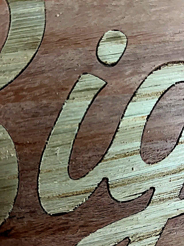
We're working on a way to combine the profiling and V-carving operations into a single "male inlay" operation that just has a single gap parameter, and handles figuring the profiling offset, V-carving maxdepth/depthoffset, and generates both of them as a single toolpath - so you won't need to remember this whole process once that's all dialed in!
- Charlie
Hi Joe,
Here's a writeup about using PixelCNC to generate toolpaths for making an inlay that I sent to another user a few months ago. Let me know if you have any questions or need help with anything :]
Here are the two project files for the ladybug inlay that the writeup refers to:
2x2x0.15_Ladybug_Inlay_Female.pnc
2x2x0.15_Ladybug_Inlay_Male.pnc
With the two project files the final cutting depth for both is 0.1 inches because this is a relatively small inlay. For a larger inlay you will probably want to go a bit deeper but I suggest starting with small inlays and working your way up because machine squareness and flex will throw cuts off and result in your inlays not fitting as well. For most inlays you can get away with a pretty small overall maximum cutting depth, there's not a lot of reasons to go deeper than is necessary - and there's less cutting with a shallower inlay, which is a good thing with hardwoods like walnut/maple.
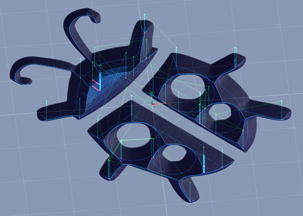
Starting with the the female side's project file we are doing a pretty basic V-carving using the Medial-Axis carving operation (found under Specialty Cuts on the Operation Type dialog when creating a new operation) which can be used to cut designs with V-bits, tapered ballnose cutters, and ballnose cutters (aka 'B-Carving'). This operation type generates cuts which follow the medial-axis of a 2D contour - either from a vector paths-layer, or waterline contoured from the canvas heightmap at a specified Z height, and the tool is moved up/down along the medial-axis so that it's filling the width of the shape.
However, the diameter of the cutter determines the deepest that we can go for a V-carving. More importantly, if a shape/design is too large for our cutter's diameter, then we end up with a medial-axis cut like this where all the areas marked red are left behind as all the cutter can do is hug the perimeter once it is half its diameter from the input contour:
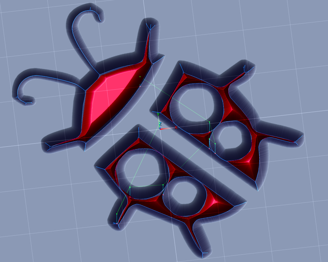
With the female only cutting 0.1" deep with a 90deg v-bit, anything that's farther than 0.05" from the design's edges will need to be removed somehow. This is why we are also including a 2D Profile Milling operation beforehand to clear out the inner areas that the V-carving won't reach by itself, unless we cut deeper (if the bit's diameter and flute length can handle it), or use a wider-angle bit - which would not be ideal for an inlay as small features would come out very thin. You'll want to use a bit with a tip angle of 90 degrees or less.
We are using a paths-layer of the vector design we want to make an inlay out of, which we can directly use as contour input for both of these operation types to generate cutpaths from. This is all covered in the interactive tutorials that come with PixelCNC.
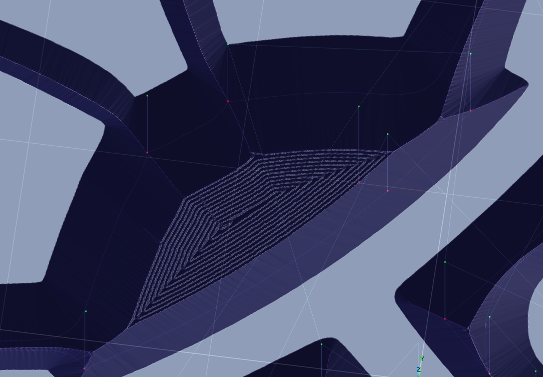
Using a V-bit to mill out the inner areas will leave tiny ridges, depending on our cut stepover, but we only need these ridges to be smaller than the headroom gap that we'll have with our male plug. In the example female project we have the cut stepover for the v-milling set to 0.005" which is a bit smaller than we actually need but on my flimsier machine this also means that my V-carving will be more accurate as the cutter won't be hogging out as much material, resulting in the cuts being more accurate when the V-carving comes through.
We could also use a different bit with a larger stepover, such as a tapered ballnose cutter, and use a larger stepover - but the larger the cutter and stepover the more likely we might end up with spots that are missed, like this situation where a 0.125" flat endmill was used to clear the area inside a V-carved area:
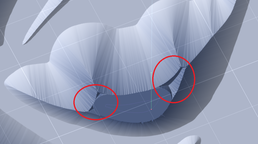
By using the 2D Profile Milling operation with a V-bit we can get in tight spots and remove these unwanted bits that will cause problems with an inlay. Here are the parameters the v-milling operation is using in the female side:
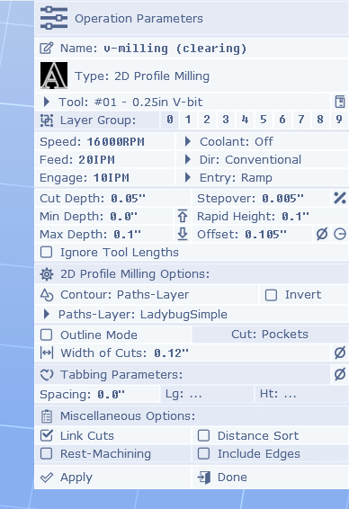
You will want to adjust the speeds/feeds for your machine, and the wood you're using, and for the cut depth and stepover being used. These are parameters you'll have to find out for yourself on your machine through trial-and-error, and suggestions and advice from other people using the same machine as you on the materials you want to cut.
In terms of an inlay, the important parameters here are the Offset and the Width of Cuts. We are cutting 0.1" deep so we want to push our 2D Profiling away from the sides of our design by 0.1", but we add 0.005" on there for the subsequent V-carving operation to come through and clean up.
The Width of Cuts parameter triggers the operation to generate multiple neighboring cuts, similar to the 2D and 2.5D Offset Milling operations, but if we had a larger area to clear we would only need this to go out far enough that it reaches where a flat endmill would come and clear the rest out - enough to get those little bits that are circled in the image above. For this project we're just using the V-bit to clear the whole area out instead.
Here's an example of a V-carving project where the V-bit was also used with a profile milling operation with a Width of Cuts to get the tight spots in the cow's head, and then a flat endmill was used to clear everything else with a pocket roughing, a pocket finishing, and a profile finishing:
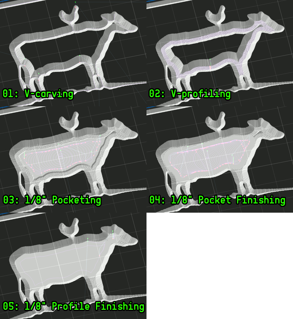
For the female side we won't be going in with a flat endmill to clear the middle, and just use the V-bit and Width of Cuts parameter to fill it with concentric offset cutpaths.
You may also notice that the Entry cut is set to Ramp, this isn't 100% necessary, just something I do to prevent a jarring force on my boingy machine!
So that's the female project, it's really just your basic V-carving but it's important that it's square in all three axes, and the machine isn't flexing and letting the cutter deviate!

The first thing you'll see is that we've mirrored the paths-layer that we're using as contour input for generating our cutpaths. This is accomplished by enabling the Mirror X option on the paths-layer's properties in the Project Canvas mode.
With the male side we have offset the toolpath by 0.025 inches so that the top surfaces of the male don't bottom out on the female side. With a 90 degree V-bit this means that this offset amount will produce an equivalent 0.025" gap between the top of our male plug and the bottom of the female side - and between the top surface of our female side and bottom of our male side (because they're both cut 0.1" deep so an offset shifts the male out of the female). This means we'll have 0.075" where the male's surfaces are interfacing with the female's. For a larger inlay you will want to have a deeper cut, such as 0.15" or 0.2". If we were using a 60 degree V-bit then the headroom would be double what our male offset is, and we'd have 0.05" of "headroom". We could use a smaller offset with a narrower bit.
Here are the parameters for the second profile milling operation, which is the important one that we care about:
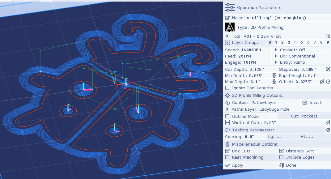
The first two operations are 2D Profile Milling operations using our X-mirrored paths-layer as contour input (shown in orange above), and we have Invert enabled so that we are cutting outside of our paths-layer's paths instead inside. Theoretically, if you could ensure that the bottom of all female cuts are perfectly flat, and the bottom of all male cuts are perfectly flat, then you could just cut the profile of the shape with a V-bit matching the V-bit used for the female, then remove everything outside of that, and make an inlay with two exactly fitting male/female pieces - with no headroom gap whatsoever. Being that we want a little room for our cuts to not be 100% perfect and not consume days of cutting time, we want to have a gap between the top of the male and bottom of the female (and vice-versa).
This image I borrowed from KrabCAM's page perfectly shows what we're trying to do:
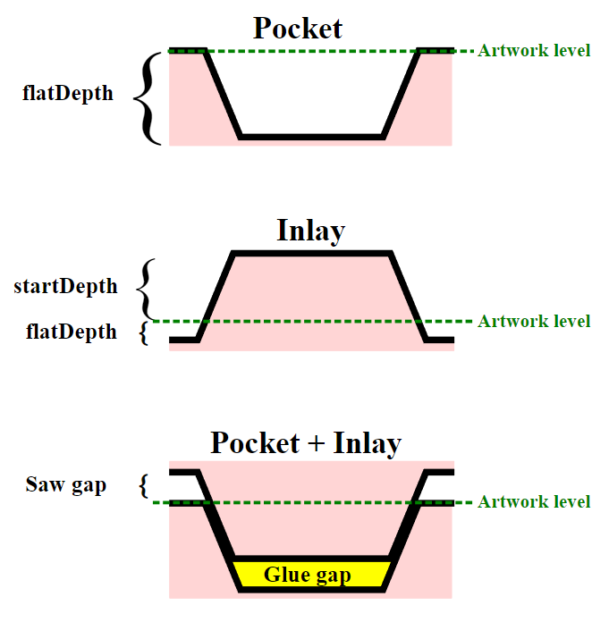
The first two profiling operations are virtually identical, except that the first one only cuts 75% of the way down, with a larger stepover, and faster feed rate. The first operation is just a roughing operation so that the second operation goes more smoothly. We use the Width of Cuts with a value set to roughly the radius of the endmill that will be coming in to remove all the surrounding material around our plug, to get the tight nooks and crannies where it won't.
The important parameters for our V-profiling operation are the cut Stepover so we don't leave any ridges taller than our headroom gap, the Offset parameter which is equal to the amount of gap we want (for a 90 deg V-bit) plus 0.0025" for our V-carving pass to come through and handle cutting the bottom, which will be the top-surface of the male after it has been glued and has its back milled off, so that we have headroom with the top surface of the female that everything will be mating with.
The situation is that because we're using an Offset on our V-profiling our resulting shape will no longer properly fit as-is into the female side. Inside corners will not be sharp enough to fit corners on the female side. This is where a medial-axis carving operation comes in and handles cutting where we want the top-surface of the female to sit on our male plug.
What is important, especially on a giant spring of a machine like my own, is that the V-profiling cuts go everywhere that the V-carving operation will, to clear material out for it, which can be tricky when there are features close together in a design. This can require preceding the profile milling with a shallower one that also has a smaller Offset, to help clear material out in preparation for the V-carving that follows.
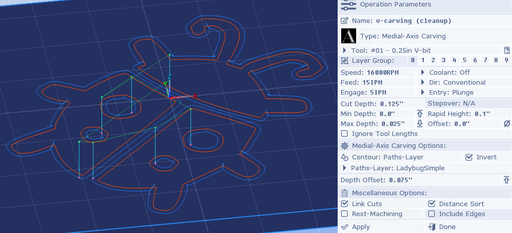
The V-carving operation is only necessary because our V-profiling is offset, which causes inside-corners to puff out and no longer be sharp 0.025" from the bottom (plus we added 0.0025 ontop for the V-carving to cleanup, but even if we didn't the offset would still make it not fit right). So to get that last bit of shaping we need so that it fits properly we are "extending" the male down farther than the design itself, that's what this V-carving operation lets us do:
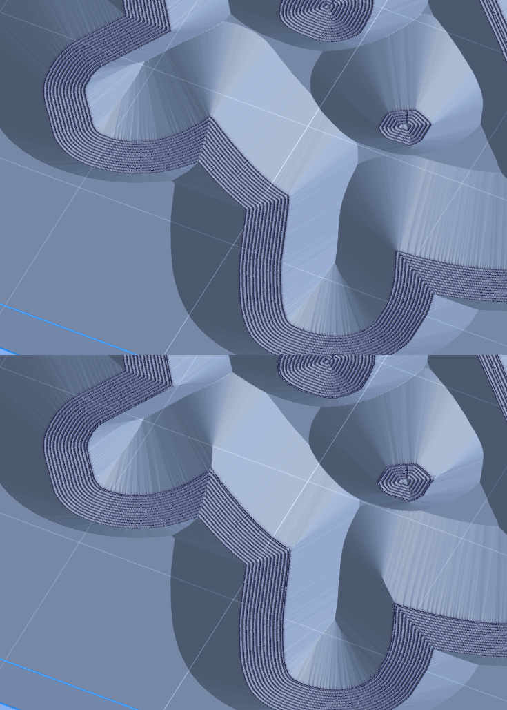
The important parameters here are the Max Depth, which should be equal to the depth of our headroom gap, which is 0.025". This won't work on its own as it will just cut a shallow V-carving in the top surface of the male workpiece which is why the Depth Offset is set to 0.075", which simply moves the generated cuts down to the last 0.025" that we want to extend out of the female - the area called the "saw gap" on the diagram from the KrabCAM site.
Here you can see how the including of the 0.025" V-carving that we've offset down by 0.075" matches our design's orange paths:
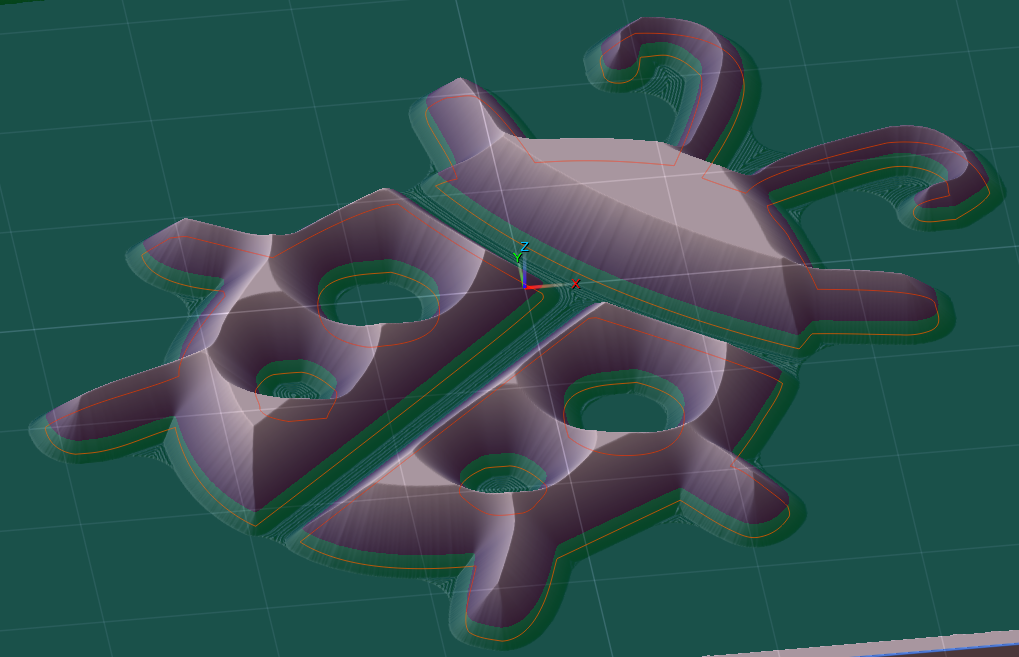
Everything green is what will be outside the female side once they are mated, and everything red will be mating with it and become the inlaid material. You can see that all our V-profiling ridges from before the V-carving operation are well below our gap/headroom, and we could get away with a larger cut stepover - at least on a machine that can handle the forces involved (i.e. not my machine).
What is important is that there is nothing that's not a part of the design that's above this plane, or it will interfere with the female's top-surface and prevent a good fit where all angled cut surfaces are mating.
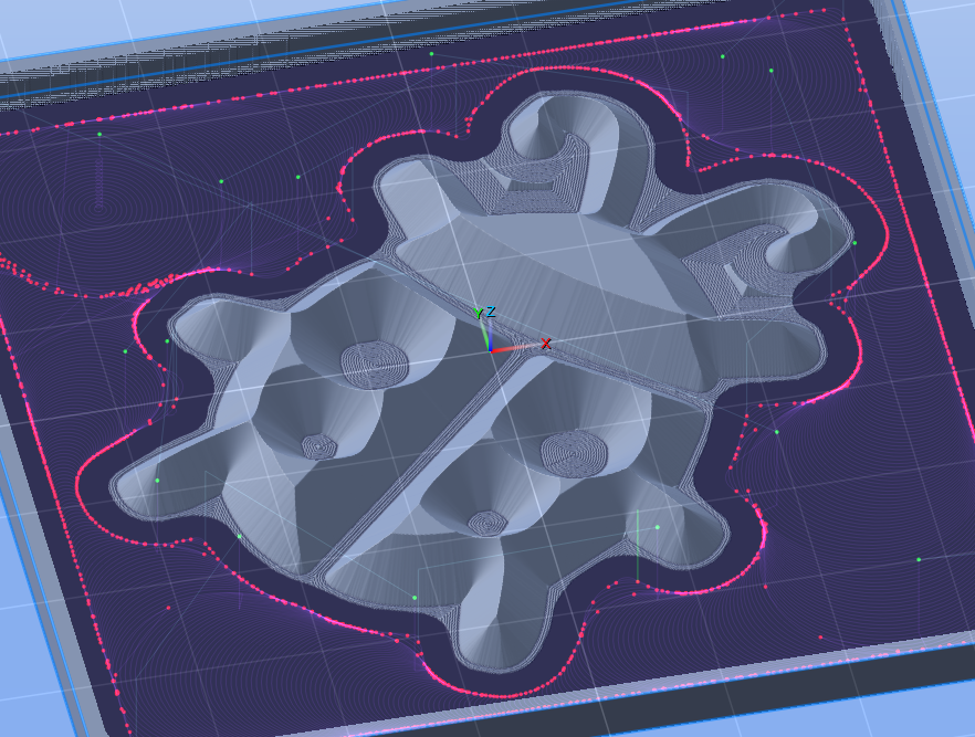
The rest of the male project is just clearing out all the material around the male plug geometry that we want it to have. In the example project file we're using a 2D Trochoidal Milling operation to mill the outside of our paths-layer using a 1/8" endmill (don't forget to enable the Invert option). You can use a 1/4" endmill and really hog it all out, it doesn't have to be perfect - as long as gets any islands of material that weren't reached by the V-profiling operations at the beginning, which you could extend out farther by increasing Width of Cuts, but you'll be adding a good amount of runtime doing that. You'll just want to make sure your clearing toolpath's Offset is large enough to include the 0.025" extension we've created (i.e. half of endmill's diameter + 0.025" + some extra, ~0.005" to 0.015" depending on the project size). Set your Feeds and speeds, Cut Depth, Stepover, and other parameters to whatever your machine can handle when clearing this unwanted material away.
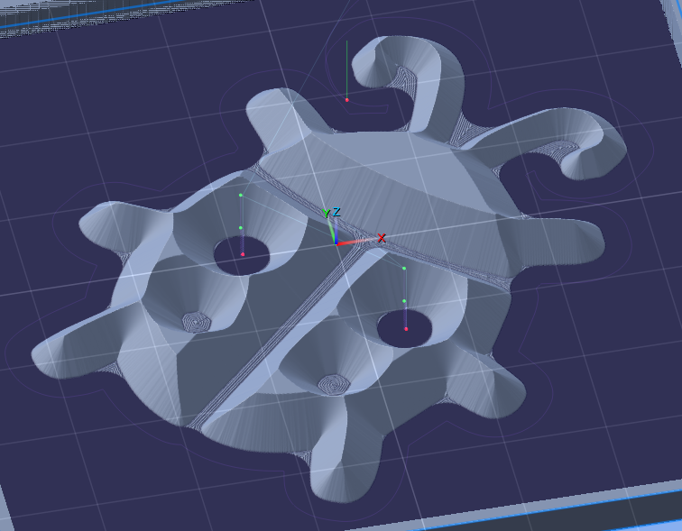
Then the last operation is just a profiling pass with the 1/8" endmill, of course offset by half our cutter's diameter plus our 0.025" gap. You could have a larger Offset and leave some of those V-profiling ridges if you want. What's important is that we get any high spots leftover, like the spots between the front legs and ladybug antennae.
After cutting that you just saw off the sides of the male so you just have the plug geometry, use a liberal amount of glue, and clamp it to the female. You should see a nice even 0.025" gap all around both pieces. Let it sit overnight then come back and saw the back of the male off, or mill it off, etc... Then sand and stain/seal, whatever you want :]
I hope that covers everything. You should be able to learn everything else you need about PixelCNC from the included Interactive Tutorials. After practicing running some G-code from PixelCNC on your machine and becoming comfortable with everything you should then be able to create this ladybug inlay, and then start working up to larger sizes. If your machine is not square you'll find out. Definitely don't jump to a two-foot sized inlay and end up scrapping a bunch of nice wood. Work your way up to it, figuring out what works with your machine and what doesn't.
- Charlie
Hi Joe,
An inlay is a bit more advanced than I feel comfortable cramming into an interactive tutorial, but a video is always a possibility - we're just not working on one at this time. However, I do have a few example projects that could show you how the whole process works!
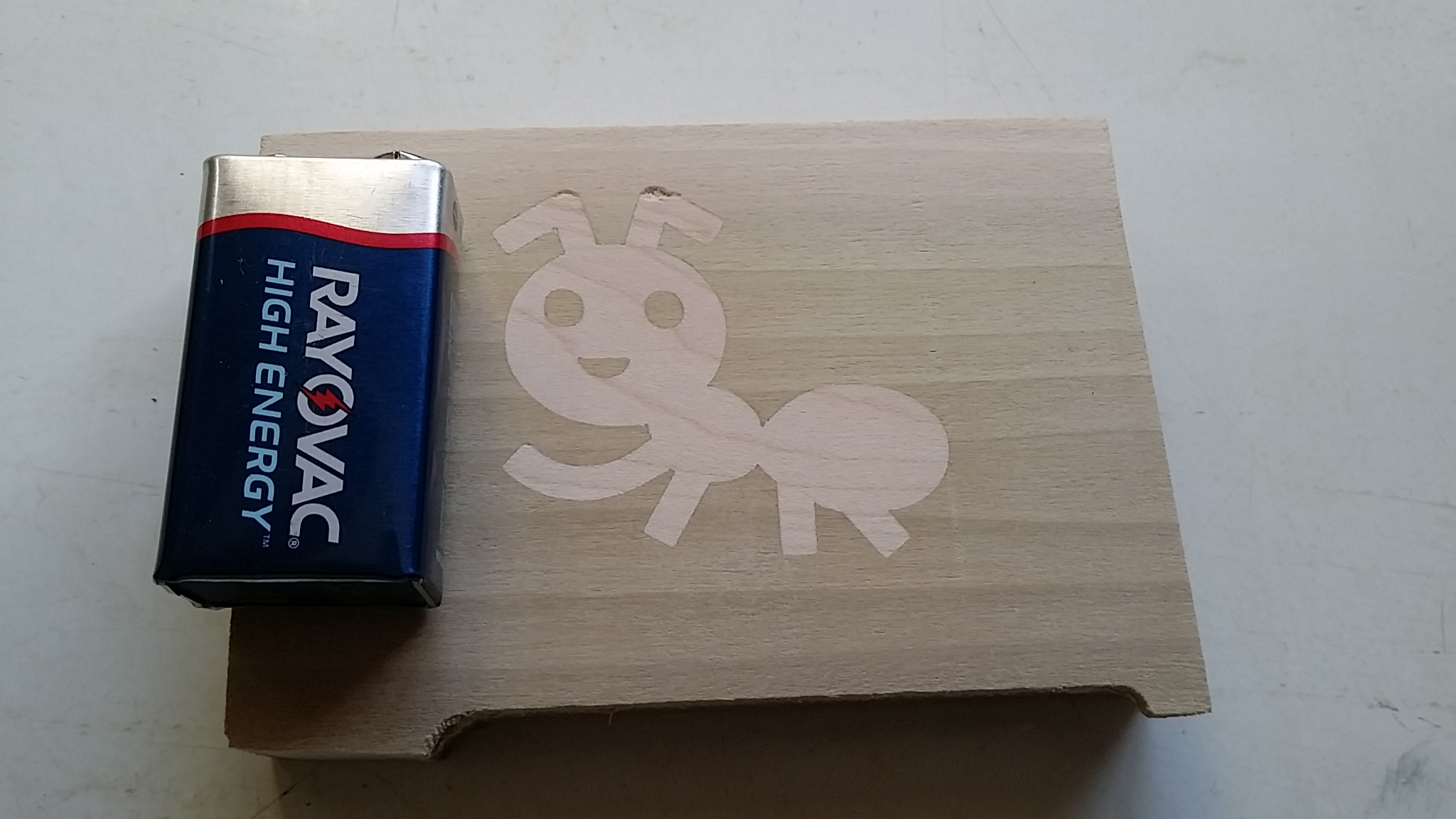
The backing on the male side was very thin and resulted in a small bit of tear-out when milling it off. I should've left it thicker so that the endmill would take cleaner chips out of it during removal.
Here are the project files that were used to create the above inlay:
Give me a day and I'll do a more involved writeup here explaining the what/why of each operation and its parameters and then you should be able to create your own inlays. The male side is the more involved part because it is where the operations' parameters are how it's ensured that there's a bit of headroom between the top/bottom of the male/female parts when they go together, to ensure that they can be mated as thoroughly as possible, like so:
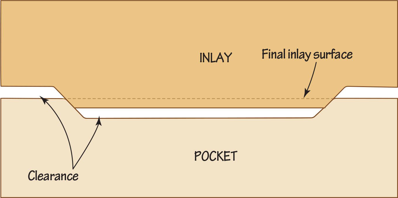
The male side is really just a combination of a profiling operation and a V-carving operation to get the bottom-most parts cut to properly fit against the top surface of the female as optimally as possible. It's also very important that your machine is as square as possible between the X and Y axes, especially with larger inlays where being out-of-square can really throw it off!
- Charlie
On the site it says no refunds, download the demo to test. On the main page it says Download Demo with all the downloads for different platforms, but none of them work. Is a demo no longer being offered because refunds are allowed now?
Thanks!
- Charlie
EDIT: Doh! The demo downloads ended up working afterall. Now I have every single one of them in my downloads folder XD
Hi NicoClock,
Thanks for sharing the operation parameters.
The machine origin for your project is set to the bottom of the canvas, which means that Z0.0 is the bottom of the canvas volume and Z6.0 is the top surface of the canvas volume. Any cutpaths generated will be inside of the canvas volume, i.e. their Z coordinates will be from Z0.0 to Z6.0.
The G0 Z6.1 is a move to the rapiding height above the canvas, because you have Rapid Height set to 0.1mm in your operation parameters. Then the subsequent XY move is to the start of the first cutpath before it feeds down to 0.6mm below the top of the canvas, per your operation's Cut Depth, which is going to be Z5.4.
It looks like you just need to move your machine Z origin to the top of the canvas, which you can do under Canvas Properties by clicking the up-arrow next to the 'Z Origin' parameter, which should set it to 6.0mm. Then click Apply and you should be able to export your G-code so that cutpath coordinates have Z0.0 as the top-surface of your workpiece, and the first layer of cuts will be at Z-0.6.
- Charlie
Hi Patrick,
Thanks for sending that over. The G-code all looks as it should. Your cut depth for the roughing pass is at 0.03", so if your machine origin is set to the top-surface of the workpiece then it will cut at 0.03" depth increments, i.e. -0.03" -0.06" -0.09" etc. The finishing pass has a cut depth of 0.02" and -0.02" is the coordinate it's bottom out the first layer of cuts at. This is expected behavior, and what you want to see (unless your cut depths weren't actually 0.03" and 0.02"!)
It's definitely a machine/controller issue if the G-code is correct - which means there could be something with how your controller is dealing with setting the Z origin when changing tools - whether it's actually establishing the absolute machine origin or just setting a tool offset or work coordinate offset somewhere that only their software knows to use.
If you're using an external tool touch probe to zero your machine's Z origin it's probably not setting the machine Z origin where it needs to be because this requires knowing where the top surface of the material is (or the bottom, depending on which you're using as the Z origin for toolpaths) as well as the exact Z distance between it and where the external touch probe surface that tools touch off on is. Different machines/controllers will handle this in different ways that is not always friendly to conventional G-code when using the separate tool probe for setting Z origins/offsets, as they've designed the probe to work with their software and their setup - leaving their end-users to figure out how to use any other software themselves. There's surely an article, forum post, or tutorial on the internet that will explain how to do this properly with your specific machine/controller.
What you want is for jogging the tool to X0,Y0,Z0 to be where you've chosen for your machine origin when running G-code.
Also, I suggest enabling the Distance Sort option when generating Parallel Carving toolpaths that use the Rest-Machining option, which will greatly speed up the runtime for finish operations by removing a lot of unnecessary rapids between cuts. Or, if the flutes on your cutter are long enough, you can set the operation's Cut Depth to reach the bottom of the canvas and have your finishing operation cut all in one go! This takes some careful consideration and requires that your machine will be able to handle the material removal varying as the steepness of the relief varies.
- Charlie
Hi Hegartype,
The two main reasons that a different tool is cutting higher than it should (or lower) is because either the coordinate space is shifted on the machine, typically caused by the Z zero being off, and/or the machine losing position while cutting - which can happen if it plunges straight into material faster than the machine's Z-axis drive motor can handle powering through.
There's also the possibility that the first operation had its Z position offset while cutting, causing it to cut lower than it was supposed to.
The test is to zero your machine's Z origin and after running an operation jog the machine to a point that you know should be zeroed out (for any or all axes) and see if the tool is where it should be - especially after a roughing operation.
Depending on the machine, a 50% stepover for a 1/4" endmill can be quite a large bite to take, and I could see a machine losing steps downward, causing it to offset downward and cut lower than it's supposed to. I've seen this when roughing out a relief carving too quickly with a 1/4" ballnose cutter on a machine that had an underpowered Z-axis.
Let me know if you have any other questions or need help with anything else :]
- Charlie
Yes if you rely on the font size parameter when text-editing to get the layer how you want then making copies of the layer to create more text with the same font and scaling shouldn't be an issue. It's only when manual scaling is applied after editing a text-layer that you risk having to manually re-scale it again if the need for going back into the text-editing mode arises, as PixelCNC enforces a certain pixel density for text-layers so that there's effectively a uniform relationship across all text-layers using the same font and font size. If one layer is scaled differently then changing its font size to match another layer that isn't manually scaled will end up requiring the use of a different font size just to get the same letter sizing.
The font size controls the number of pixels used to rasterize the text using the selected font, and accommodating for manual scaling means a user could effectively make the font size inconsistent, and scale up a text-layer with a small font size, which would result in a text-layer with very pixelated looking text! That's why PixelCNC calculates a new size for given text/font/size, to maintain a consistent pixel resolution for the text itself.
I suppose it's theoretically possible for PixelCNC to somehow determine the optimal text rasterization resolution for a given layer size, but then there'd be no way to control the absolute lettering sizing so that it's consistent across multiple text-layers, then you'd be stuck with manually scaling text exclusively.
- Charlie
Hi Joe,
The text-layers will dynamically resize themselves per the text size used when editing them, and any manual rescaling of the layer will be replaced. The best thing to do is not rely on manually scaling text-layers and instead only use the text size parameter while the text-editing mode is enabled to get it to the scale you want, and let PixelCNC determine the size of the layer for you.
The ability to manually scale a text-layer is really only meant for fine-adjustment when the text will no longer need any further editing - which includes changing the font and character spacing. :]
- Charlie
Hi tdomask,
Would you mind sending G-code output by PixelCNC, EstlCAM, and the OpenBuilds CAM to us support@deftware.org? We should be able to get to the bottom of this by comparing the output of each. The situation is likely that the machine is expecting a tool Z offset which their CAM includes a command for in generated G-code.
- Charlie
Hi tdomask,
Where the machine origin is shown in the 3D view is where you must set to be the coordinate 0,0,0 on your machine - and you'll likely also want to make sure any kind of work coordinate offsets are disabled as well. If you set the top surface of your canvas to be the project's Z origin then you should be zeroing your machine's Z-axis with the cutter touching the top surface of your workpiece. If there is any kind of tool Z offset this will affect things as well.
Keep us posted!
- Charlie
Hi Geoff,
Hrm, that's very interesting that the Stamp Size value knob doesn't behave properly for you. I'll have to do some more investigating. In the meantime I'll make sure that increment buttons are included on there, and look into what changes need to be made to include an editbox button on value knobs - or an equivalent solution of some kind.
Thanks for the feedback! :]
- Charlie
Hi Geoff,
Left-click-drag the value knob up/down to change the value. The faster you move the mouse the more the value will change for a given cursor travel distance. If you look at the GIF animation I shared previously I am just dragging the Stamp Size parameter up and down, and when holding SHIFT it changes from 0.0mm to 250.0mm very quickly with a single quick mouse motion.
There is a possibility that your mouse cursor speed is set extremely low in Windows, which will require moving the mouse very fast and far to get a cursor speed that will produce the exponential value change - but then interacting with the 3D view and manipulating layers by their handles would also be very slow I would imagine.
PixelCNC's UI assumes that your cursor can be moved from one side of your screen to the other without picking up the mouse, with a single wrist motion. If your cursor sensitivity is turned down I can also add an option to the UI Settings dialog for tuning the sensitivity when interacting with everything, if you think that would help.
Let me know what you think. :]
- Charlie