Charlie.....
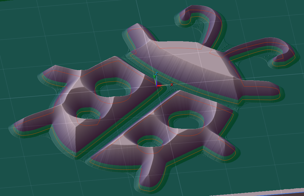
I can't get my simulation to look like this..the division between the green and purple at the bottom. What color setting do you adjust. Mine is all one color. I've tried different combinations. Burning question of the day....
Thanks Joe
Hi Joe,
That was a bit of a contrived screenshot there just for demonstrating the purpose of the operation parameters that are used. It wasn't meant to be something that users should be able to see and/or reproduce. I don't remember exactly what I did on my end to create it but the fact that it's showing a paths-layer in orange while also showing the red/green contouring Z-plane tells me that it's something that users won't actually be able to recreate with the public release of PixelCNC as there's no situation/function/mode where both a paths-layer and a contouring plane should be visible at the same time. I did something in PixelCNC's source code specifically to create that image that isn't present in the public versions.
The screenshot is only meant to show how the green area at the bottom is what the V-carving operation results in, as a sort of extension off of the original base design to form the "saw gap".
- Charlie