Indie game storeFree gamesFun gamesHorror games
Game developmentAssetsComics
SalesBundles
Jobs
TagsGame Engines

valhallaCNC

85
Posts
23
Topics
A member registered Dec 24, 2021

Recent community posts

Charlie...

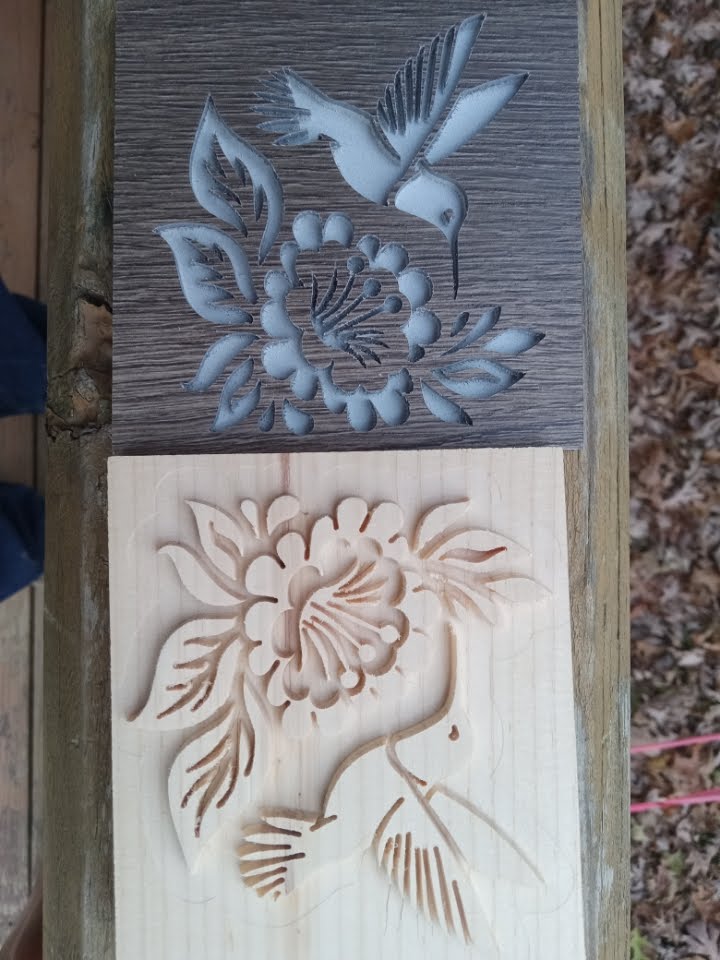
I just had to try one more old way...The brown is  vinyl floor laminate, a little fuzzy I never cut plastic before. I need to tune my feeds and speed. I offset the female a tiny bit. Depth is .15 10.5 degree Bit. They fit perfectly together. This topic is now closed....

Joe..


Charlie....

So now I have "Old Way Knowledge".... I'm ready to learn the New Way....Get rid of my obsolete brain cells.

Joe..

(1 edit)

Charlie...There is a difference in the Gcode...When none is the option it does not output the block. when off is selected it issues the off command. Myself I would like the none option...

Thanks Joe...

(2 edits)

Charlie...

I use coolant control as a M0 (stop) command that works for me, between operations

One thing thou...after you pick a coolant in the tool operation you can't go back to None as an option

Thanks Joe

Thanks Charlie...

I'll work on it custom post,  I try to keep you busy...Nice to have an estimated run time  for each operation.  BTW your estimated times in simulation are way off from actual.

Joe....

Charlie...

I do log slices, I flatten them before carving. I can do your suggestion with a small canvas z . A lot of times I have to do multiple passes. Is there a way to pause gcode between z changes. Example: If I want a total depth of .4 with a .1 cut , so from . 1 to .2 to .3 it would pause between z changes so I can  decide to continue or terminate.I never really know how much I have a to remove.

Thanks Joe

Charlie...

 I've been using a free surfacing gcode generator. Is there a way to create a surfacing tool path ?

If not maybe as a create new layer ?

Thanks Joe...

Charlie..

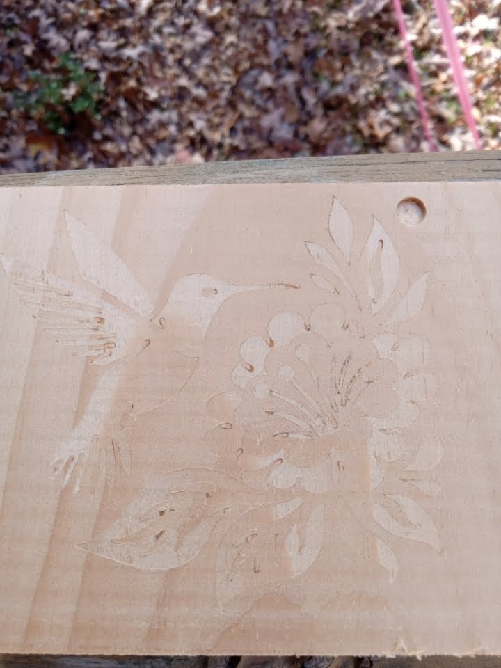
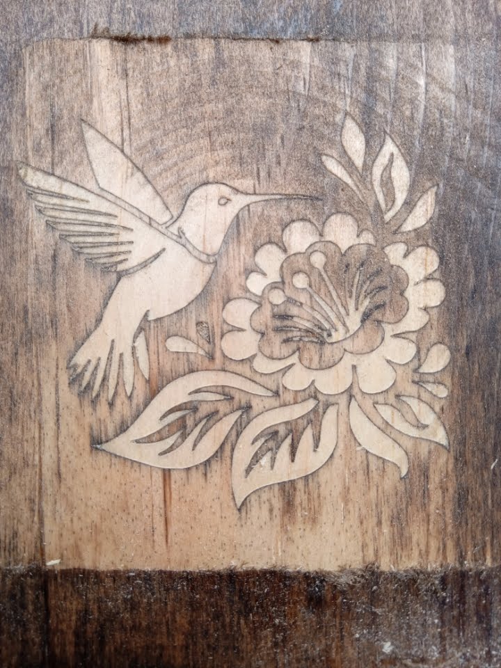
Final test at 10.5 deg at .15 depth.  This was in scrap pine, I'll never use sharp angle like this just a proof of concept. Surprised at how much detail could hold in soft pine. 

Joe....

Charlie....

I tried a 10.5 deg inlay. While the male fit in I couldn't seat it deep enough, think I have to offset one of the other to make it fit. All the missing pieces are because I didn't let the glue dry. I knew it wasn't seated correctly so I rushed ahead. That's not much of an angle needs some tweaking but it does work...no wonder I couldn't duplicate that color...Joe

Charlie.....

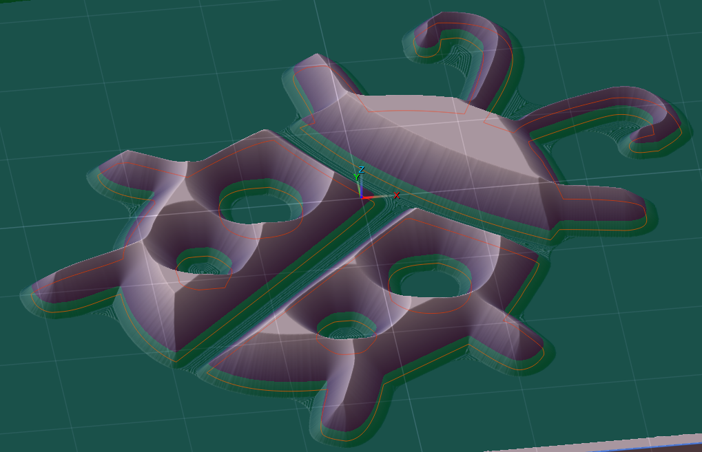
I can't get my simulation to look like this..the division between the green and purple at the bottom. What color setting do you adjust.  Mine is all one color. I've tried different combinations. Burning question of the day....

Thanks Joe

Charlie...

All the tear out occurred in the male piece before glueing. None occurred when I milled the waste off. The inside of the flower and some of the leaf ends were so fine a detail the pine could not hold it. The gaps are all tight the stain was still not dried when it was glued up. I was thinking a bit with a sharper angle to get a little  deeper and a  bigger saw gap. I've seen inlay videos where they were use 15 degree bit... I'm going to try again...

Charlie....

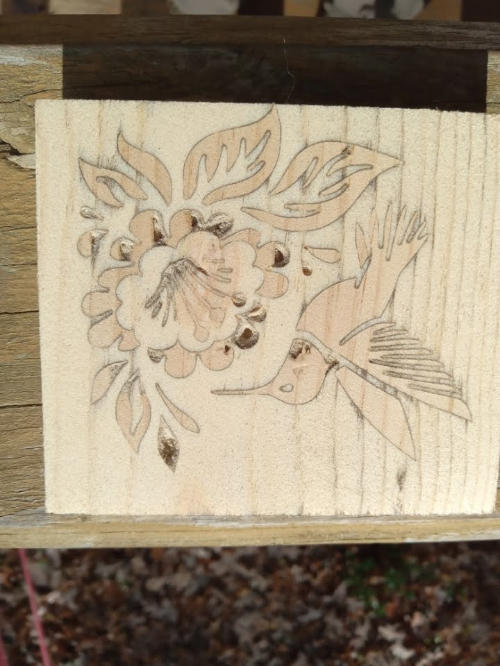
Cut my first inlay with 60 deg bit, .1 depth. This was just scrap pine , some of the very fine details got lost because of tear-out. This was a 3 x 3 hummingbird. Pretty happy with this result, I believe if this was a better wood it would have come out way better.

Joe....

Profiling..V carve ..pretty much any operations parameters that use offset as one of the settings...you already have offset by tool radius just update that setting button.  To do calculations on vbit deg and depth of cut. 

Charlie....

Just a thought. On your offset number you already know your bit geometry and your depth of cut. Can't you calculate that automatically, similar to your canvas top and zero out option. Give you a starting point to add or deduct from there. This would work in all your offset situations not just inlays.

Thanks Joe

Thanks Charlie...I was trying to calculate that. After you showed me the example, I checked my calculator it was set to radians. No wonder I couldn't figure it. I know you can do the calculation in Pixel, just easier to use calculator..(except this time). Sounds like a good addition the numbers seem to all follow your depth of cut. Only difference I'm seeing is the details in the design for your bit selection.  I'm close to trying a cut with a 60 deg bit. 

Charlie...Going over the details of female inlay. Don't know where you got your .105 , I know why the .005 but can't see where you got .1 ( important parameters here are the Offset and the Width of Cuts. We are cutting 0.1" deep so we want to push our 2D Profiling away from the sides of our design by 0.1", but we add 0.005")....how did you calculate the 0.1 or it just depth of cut ?

Thanks Joe...

Charlie....

Thanks lots of info to go through.  I'll give this a try soon, let you know how it works out.

Joe

Charlie....

No Hurry it's a future project a little ways off.  Thanks I'll check out your examples this week,

Joe

Charlie....I want to try some inlay projects. You have one picture of inlay in progress. I didn't see anything on your tutorials or YouTube. Are there any available ?

Thanks Joe 

Charlie...

That works fine , what I did on the first one I resized text layer manually to fit better. I compacted and made the font taller. When I did that I changed the whole font characteristic so there is no way for me to duplicate it easily. No way to make the text layer static ? The percent would work then ? As usual I do things the hard way....

Thanks Joe..

Charlie..

I have a street sign project I'm starting. My canvas size is 5.5 x 32 for the first one, I make my text layer with street name EG. Hollow Cavern Road. I size it to fit . My question is when I edit the words ,even taking the "d" out of road and putting it back the text layer changes size. the percentage in the font stays the same but I have to resize the text layer after editing.  Every sign will have a different length, but I want the font size identical. The way I'm doing it now is trial and error by matching letter size. I must be missing something..Is it something in my setup that's wrong. I've tried several things, the text layer dynamically changes it's what is messing me up I think. Any help would be great..

Thanks Joe

Don't know about Dremel they have a much higher RPM, nylon fingers will be a lot shorter I'm using 3" diameter wheels on  cordless variable speed drill. 

The ones I have they are made of nylon and very flexible, with the different grits some are pretty gentle. Even with softer woods and using a lighter touch I haven't found them to be harsh. I've used them for detailed carving with great results. You have to follow the cuts not across them, but can go against the grain just fine. I think it's mostly the pressure you apply, but pretty simple to use.

 A bit off topic....  I've been using these for awhile , been great for sanding after cutting. Come in different grits they work well. Alligator looks great.

Thanks  Charlie....

I've never explored those tools. A lot of options there to go through, I've never needed them . The card got me curious. 

Thanks Joe

(1 edit)

Hi Charlie...

I got interested in your final example. I tried to recreate what you have done. I've tried several ways and can't get my sleeves looking nearly as good as yours . Would you mind sharing your method to get there ? It seems simple but it is not, would make a good video tutorial perhaps ?

Thanks Joe

The type of wood you choose will be very important to get the fine details to avoid the tearing out of the grain. Looks good Charlie. 

Hi Charlie,

I was going to update my tool library. I have old tools I want to remove, also want to rename some existing ones. I need to add new ones. I know how to do all of this. My concern is all the projects I have done. I believe each project stores the tools needed for that job. How does the project recognize the right tool, is it by name, tool number, or some other way?   By renaming or reordering does the project tools get messed up ?  Hope that's clear enough...

Thank Joe

Hi Charlie..

I got that part, sorry my question wasn't clear enough. I was talking  about the actual g-code file itself. At the top of my g-code I manually put comments about canvas size(x-y-z), point of origin and the tools I need for that project. I was asking about editing the UCCNC Post Processor File to be able to include that information automatically . I don't see any options about that. Hope that's better explanation, questions seem so clear before coffee...

Thanks Joe...

Hi Charlie...

I do different size projects, my projects are mostly one off signs. My canvas is always a different size and my origin point changes. Is there a ways to add canvas size (x-y-z),also point of origin in the header, and tools needed for entire project automatically ?  I add all these thing manually now.

Thanks Joe

Thanks Charlie...totally missed that in the users guide.

Joe

(1 edit)

Hi Charlie..

I did a project that was narrow along the X axis , but very long along Y axis. When I generated a tool path with parallel carving, the tool path would be X axis  direction only . Is there a way to make it cut in the Y axis direction ? I looked at your tutorials and options for the cut but did not see how to do this. When it generates the tool path does it look at which is more efficient ? 

Thanks Joe

(1 edit)

Hi Charlie...Long time

Been busy building  new shop, question of the day for you. I finished a project , and was fine tuning it. I was trying to compare before and after changes. The only thing I could come up with is starting 2 pixelcnc side by side. Is there a way to do this on one canvas ? Something like a view only mode for the imported item. I did try to take a screen shot and open that, but that didn't work for me.

Thanks Joe...

Looks great...I know nothing about Lithophanes, How deep are the cuts to get that effect ?

(1 edit)

Hi Charlie..

Working with text on a circular path. I generate my layer with text on a path , works fine . I use position offset to get it to the top of the circle. However when you get too many letter position offset max's out at 1 , cant center it to circle path top, when text is centered on the circle it seems. I have to generate the raster layer, and use rotation of the raster layer to complete positioning. Is there a reason it max's out at 1 ?  Not an issue just a question.

Joe....

This is not a program issue, just trying to understand better...After I create the image layer. Then I rotate it -90 , then stretch it to 47 along the Y axis of the canvas . but the image is stretched on the X axis to 47.  I was expecting to see the X - Y size switch on the image after I rotated it 90. Clear as mud...I make things harder then they are sometimes..

Joe...

Laying out large sign. Canvas X=24" , Y =48" .  When you create a image layer or text layer , It is always created on the X axis. I can rotate it 90 degrees and size to fit canvas but it keeps the original import orientation. the created layers have X=46 , Y=22 after resizing . Is this correct ?  , doesn't make a difference in the final product.

I found a nice third party utility. Looks like it will do the trick very easily. Only does two parts , but that is enough for me this time.

Joe..

(1 edit)

Hi Charlie...

I have the opportunity to do a large sign. I know there is not a tiling function in PixelCNC. I'm not even sure you call it a function.  Is there a work around for that ? I am going to try square layers abutted with the words and design on top of that, with some registration holes to line everything up. Or am I way off base here ?

Thanks Joe.....

(1 edit)

That works great ...Makes work flow much easier....very nice how it updates the project tool list when you change tools in the operation tab.

thanks Joe......