Run as admin
eric berg
Recent community posts
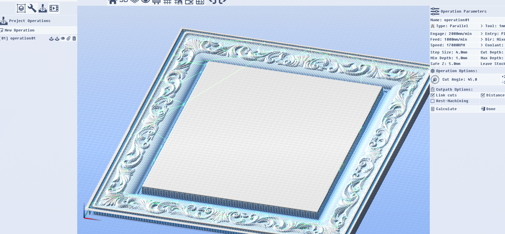
That does work. but Rest only works on the horizontal looking back at the parallel. Lots of rapid moves. I've relaxed the stepover on the parallel as I was keeping that tight to avoid the scallops on the z changes.
you don't have the link paths or sort working on the horizontal.
A new path called Z-finish that sets cut size to 0 would be intuitive. ?
a better path named Steep/Shallow where you can determine the stepover and stepdown with a transition angle default around 80?
I'm going to run the ''combo" of the 2 with a 0.3mm stepover and 0.3mm stepdown to see if the time and look is better then a tighter stepover only.
Future able to calc the runtime ?
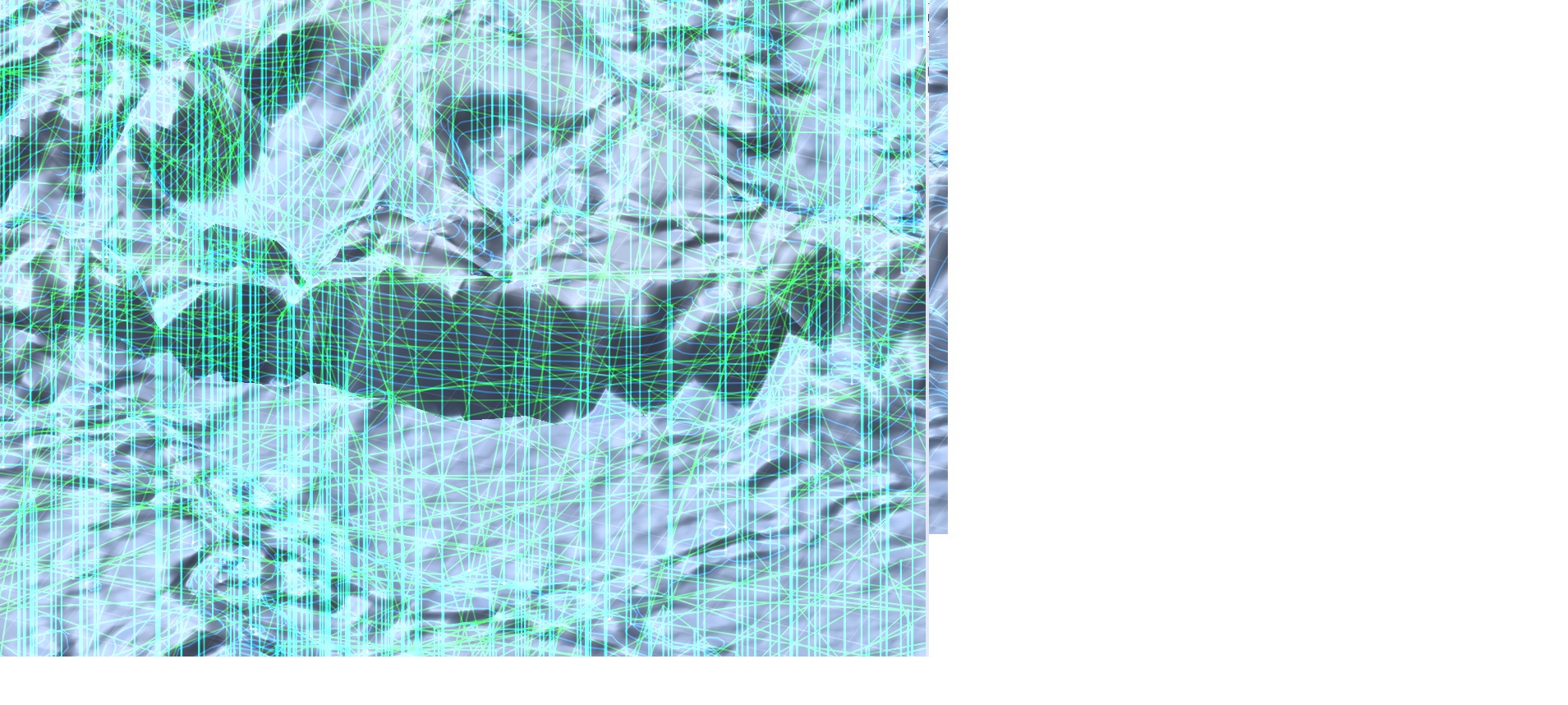
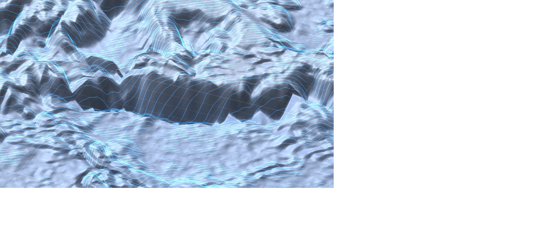
I'm trying to use conform to give a better z finish on steep areas but controlling the stepover vs flat area and missing area without too much z finish in others.
would another optional tool path type better suite that or would you plan on adding a z finish option .?
maybe combo with a deviation angle between a planner and a steep finish stepover x.x stepdown x.x @ % angle?
Tab does just that.. solves the function in current box and moves to next.
I was a code geek in a prev life. but that was 35 yrs ago. :) I did come out of hiding for Y2k to solve some govt problems with fortran and Ada, Modula 2 and Pascal. All the logic is still there, I would have to relearn all my syntax though. I do mostly M.E. now and proof it out on the CNC.
I know.. I'll post out some small programs with diff var. and reset the machine and controller each time to ''wipe': to see what happens where.
i'm cutting a 2k job while i'm trying to debugg but also getting working results. soooo figurn' out what is / isn't working while it IS working is more of a study in perplexity atm :)
Between my cnc at home, yard work, a hot wife, garden, and smoking lots of meat.... busy, happy man!!
can we have a pined post for pics that you can Moderate *edit*? i'm sorry i'm not a youtube guy to promote your program .... I think this can be worth an easy 350.00 just needs more push!!
eric
OK, it is the G91.1
I put // on that line all is fine.
CodeInches "G20" // inches mode (Inches/Metric determined by Units above ^^^)
CodeMetric "G21" // metric mode
// Distance modes
CodeAbsolute "G90" // absolute distance coords//CodeRelative "G91" // relative distance coords
// Spindle
CodeSpindleCW "M3"
CodeSpindleCCW "M4"
Hi charlie.
I will log the crash. loading in a canvas that is aprox 18 x 35" and a 2500 x 5000 ish png. if i push the dpi on the canvas up over 120 ish is where i was getting the crashes.
REST: ah. you are looking back at the prev operation. ok. my software i'm either defining the prior tool used or a specific operation.
I haven't sorted out the issue with the g code. as stated it runs off inf if i just try to run your post, but if i run an old program, stop it, then load yours it runs fine.. something is getting 'set' from the first program. I have to reboot the software to reproduce the run off from Pixel cnc code.
Did you sort out if it would be easy to change tool path generation to center of tool or give us a button for it?
thanks for your feedback.
I have found or worked around everything that might be an issue. I also haven't explored all the different aspects of your software as of yet.
I'm not sure how your calculating your 'rest' if you are not specifying what tool your are resting off of. again, i might be missing something there.
I know i have enough memory but i get a crash upping the dpi on canvas or loading in a large png. 2500 x 5000 ish. I'm only on a 2'x3' table and currently I would need to ref off one 0,0,0 bottom left and setup multi pixel projects to cover the bed with a lg file in Tiles. all ref from one G. it would be really bad if i had a 4'x8' but the wife wouldn't let me spend that much $ lol
Please bear in mind I'm coming from a professional side and not hobby cnc.
A. I know many hobby cnc set tools z0 on top of the stock.bad, bad.
1 you need new scrap or un cut top to set another tool.
2. imo stock z0 should always be bed. easy to not cut into bed with no neg z in g code.
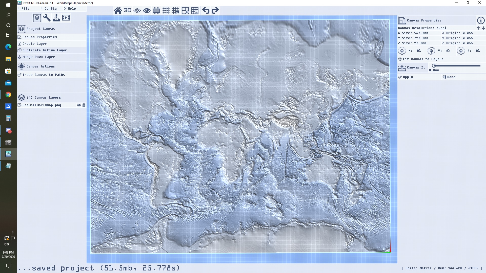
B. your ''canvas" sets the tool limits to the R of the tool instead of tool center.
IMO I don't need to define a canvas with + 0.5" per side and Z min depth of pic area 1/2ball . so I can cut a whole picture without fudging canvas vs pic if the tool paths just generated to Center of tool.
Still learning your software, just observations and maybe some help.
I'm running Mach3 at home. w a 2' x 3' table. a 60 90 from china nice place in Chicago. I would have to look at the board/mfg to tell you more.
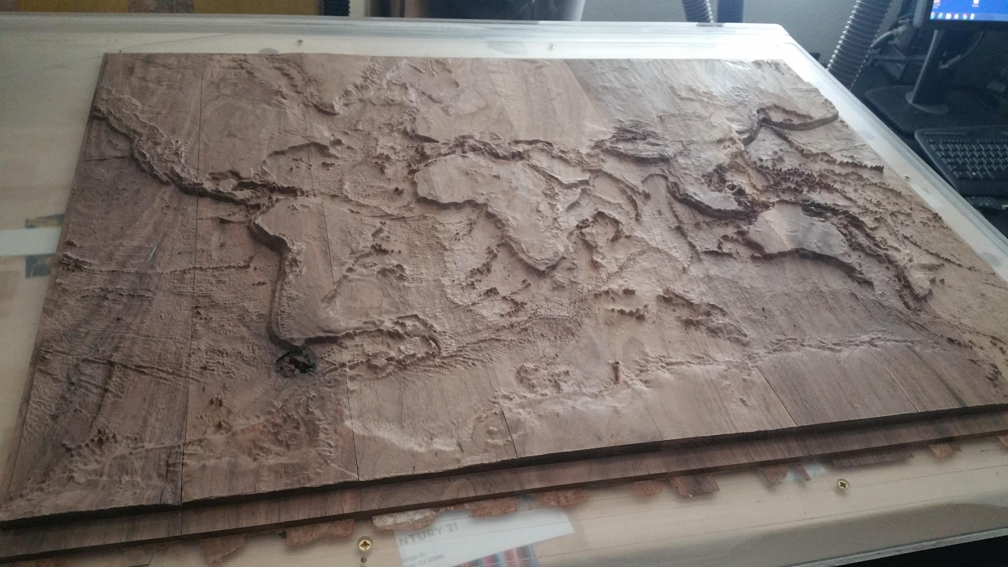
I'm a professional prototyper in the bay area. At work i use Haas mills and Surfcam, but at home i'm doing topo maps and stuff and my pro software doesn't handle STL files well and doesn't do nice heightmapping like your system. easiest 180.00 i ever spent.
I hadn't had the time to pick out what might have caused the issue. in mach3 display the toolpath just went off positive in x for ever.
i'll add in that g40
in 25 years anytime i've needed to modify a post, i had to relearn it. as I've needed to do that about once every 3 years.
oh.. and took some digging but I found a nice gray scale mapper that is much easier to use then the USGS
might want to pin it.
https://tangrams.github.io/heightmapper/#11.375/39.0487/-122.8176
I need to sort out why the post you generate for mach 3 metric ran out in X .
BOLD copy pasted the header from one of my other programs to make it work.
program ran fine like that and ended.
%
O0001(TABLEDECKOUTER)
(MACHINE: MACH3.M3)
(RUNDATE: 1/5/2020 TIME: 10.31.33 AM)
G00 G17 G71 G40 G80 G90 M05
T02 M06
G00 G90 G54 S17000 M03
*( Generated by PixelCNC v1.43a )
( Post: Mach3 Metric.txt v1.10 )
G21 G90 G91.1
( Spindle: CW 17000 )
M3 S17000
( operation01 1mmball )
G0 *
Z44.00
X199.99 Y0.01
G1 Z19.00 F350
X199.62 F600
X198.44
X197.27
X196.10
X194.93
X193.76
X192.58
.
.
.
X198.19
X198.63
X198.97
X199.46 Z18.88
X199.76 Z18.90
X199.89 Z18.98
G0 Z44.00
( Spindle: STOP )
M5
( End Program )
M30


