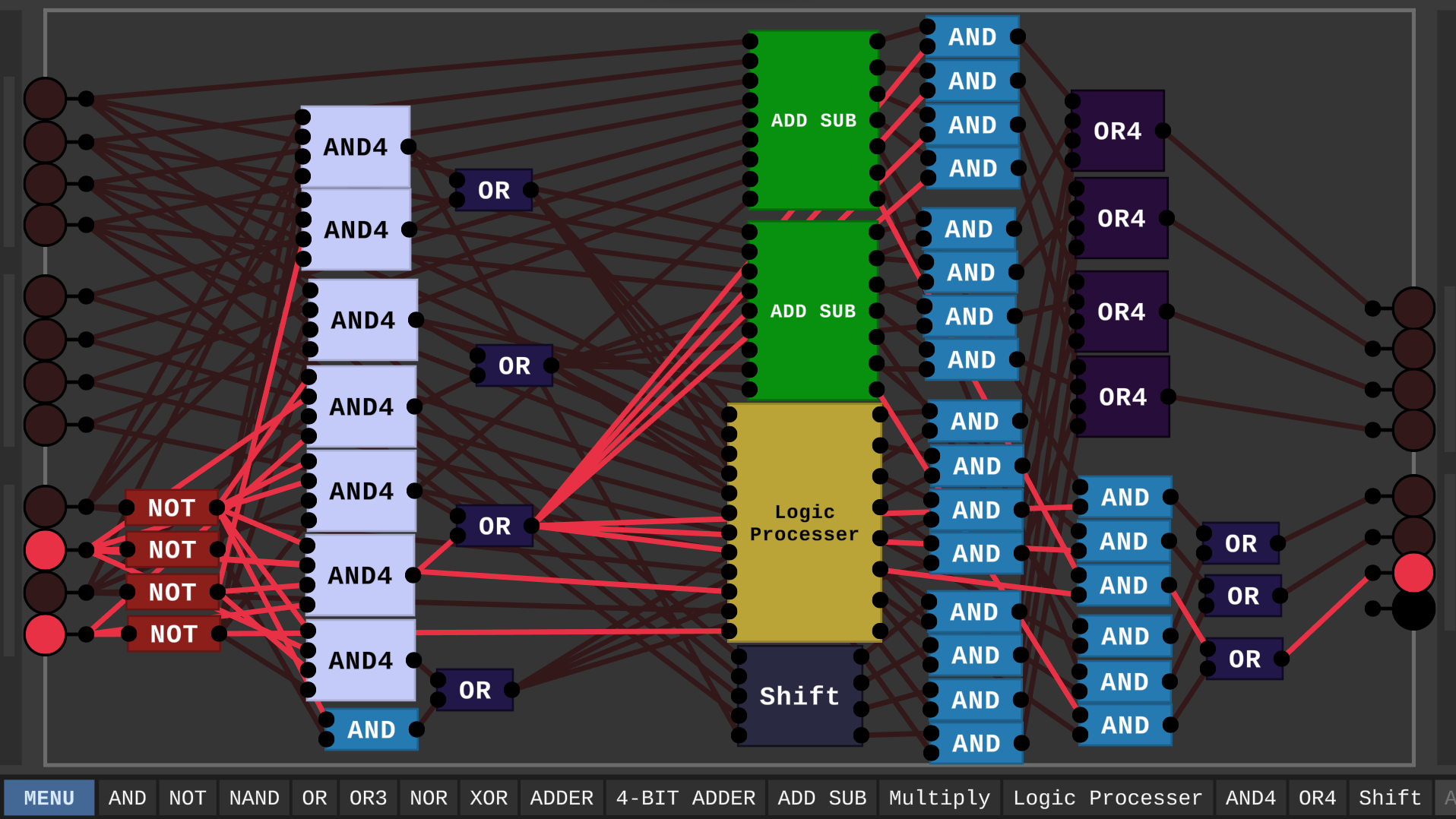
I made an ALU in the DLS with:
And, not, or, xor, add, subtract, increment, decrement, Shift Left, Shift right
The ADD SUB chip is just seb's alu
That would be very interesting to play around in, but would be difficult to implement because of the inputs and outputs. They could be placed in the plane where they were created, but then there is the problem of having to travel around and look for the inputs and outputs. Still fun to think about though.
I got a zoom/pan feature working for the previous version without too much difficulty, I don't think I have the code anymore but it wasn't more than ~40 lines of code total. The other PRs on the GitHub also include a very nice bus implementation that you may be interested in taking notes from. One issue I did notice with the zooming is that while the internals of a chip could then be any size, the number of pins were still limited by the sides of the chip, and busses alleviated this problem mostly but not completely. It might involve some restructuring, but adding pin chips that can be placed in the workspace would likely solve this issue.
https://github.com/DigitalLogicSimCommunity/Digital-Logic-Sim-CE/
Most community changes are kept here. I'll try and reimplement some of the QOL features I had added and get them in a PR in the next few days.