Indie game storeFree gamesFun gamesHorror games
Game developmentAssetsComics
SalesBundles
Jobs
Tags

I figured it was only a matter of time before some sort of emulation/virtual machine was made in Senbir.  But...I'd basically figured the first would be a glorified bootloader, sorta like what I set up in the multitasking kernel.  This is...stupidly impressive, to vastly understate it.

(I really need to just get around to releasing the current update.  Been horrendously sidetracked by Warframe & working on/off on Astronaut Plus Skateboard lately.  Well, that, and also the RISC-06 system...did I post about that yet?)


If functionality breaks in Default mode, I'd say it's probably not compatible/doesn't fit.  Especially if that entails Unity blowing up - it'll almost certainly throw a fit about the array being out of bounds if one tries to copy the emulator onto the Default mode disk.


Makes me wonder how feasible it would be to make swap a thing; it could potentially get around the issue of RAM being nigh-on useless if you used RAM solely to hold a swap system that can use part of a disk (or a whole disk, when/if I get around to adding multi-disk setups to Custom Mode) - programs would suffer a performance hit, sure, but on the flip side, you get more RAM to work with, dynamic address remapping (means your programs don't need to sit sequentially in ram, which would make memory management so much easier), and maybe marginally less self-modifying everything.


I can't say as that I have anything smart to say about the slowdown, so just: whoa.  That's impressive levels of performance drop.


I'm not entirely clear on the finer details of multithreading/multitasking, but I can see how this would make for a decent multitasking system.

(Also: if "secret higher-resolution" mode on the monitors is extended SETDATA ops; those were absolutely not intended to provide a max resolution increase.  If the game doesn't explode violently when you go above 32 bits for color+width+height?  I have no intention of changing that - unintentional cool features are still features!)


(Also, once again, pre-emptive apologies for loopiness & lateness and such.  I really, really need to go to bed at more sane hours.  And, like, not procrastinate until going to bed at insane hours is necessary >.<)

(3 edits)

I don't remember seeing any posts specifically about RISC-06, but I may just have missed it.

I do remember us chatting about the possibility of other CPUs though, and seem to remember some chat about RISCy ones as part of that.

I think I mentioned that I had designed a RISCy ISA that encompasses the functionality of the original TC-06 instruction set - but I don't think I posted it. It's not perfect by any means, but just in case it might give you any useful ideas (seeing as you're apparently building something like that), here it is (well, I ended up improving it a bit before posting it, but it's more or less what I had):

R0 = 0 : writes are ignored, reads always return 0
    while this could be just a convention, we're enforcing it to be sure
    (IRL it's (in part) to avoid spending chip area on the memory for it)
R1 = PC : program counter, aka instruction pointer (IP)
    the address of the next instruction to be executed
    incremented before executing the current instruction (easier that way)
R2-R15 : general purpose, for use by programs

0000: NOP    zero28
0001: HLT    reg4 imm24                    // HLT src ticks
                                             // wait (src + ticks2) cycles
                                             // 0 means forever
0010: LOAD   reg4 reg4 imm20               // LOAD dst addr ofs
                                             // dst = mem[addr + ofs]
0011: STORE  reg4 reg4 imm20               // STORE src addr ofs
                                             // mem[addr + ofs] = src
0100: JMPEQ  reg4 reg4 reg4 imm16          // JMPEQ src1 src2 addr ofs
                                             // if src1 = src2
                                             // then R1 = addr + ofs
0101: JMPGT  reg4 reg4 reg4 imm16          // JMPGT src1 src2 addr ofs
                                             // if src1 > src2
                                             // then R1 = addr + ofs
0110: ADD    reg4 reg4 reg4 imm16          // ADD dst src1 src2 val
                                             // dst = src1 + (src2 + val)
0111: SUB    reg4 reg4 reg4 imm16          // SUB dst src1 src2 val
                                             // dst = src1 - (src2 + val)
1000: MUL    reg4 reg4 reg4 imm16          // MUL dst src1 src2 val
                                             // dst = src1 * (src2 + val)
1001: DIV    reg4 reg4 reg4 imm16          // DIV dst src1 src2 val
                                             // dst = src1 / (src2 + val)
1010: REM    reg4 reg4 reg4 imm16          // REM dst src1 src2 val
                                             // dst = src1 % (src2 + val)
                                             // This is remainder, not
                                             // modulo, in both C# and JS
1011: RNG    reg4 reg4 reg4 imm16          // RNG dst min max val
                                             // dst = random(min, max + val)
1100: PMOV   reg4 reg4 imm5 imm5 imm5 imm5 // PMOV dst src destB
                                           //      fromB endB rotB
1101: PSET   reg4 imm5 imm4 imm1 imm14     // PSET dst dstBit numBits
                                           //      clearRest valueBits
1110: DLOAD  reg4 reg4 reg4 imm8 imm8      // DLOAD dst dev addr ofsD ofsA
                                             // dst = device[dev + ofsD]
                                             //       .value[addr + ofsA]
1111: DSTORE reg4 reg4 reg4 imm8 imm8      // DSTORE src dev addr ofsD ofsA
                                             // device[dev + ofsD]
                                             // .value[addr + ofsA] = src

Note that "ticks", "val", "ofs", "ofsD" and "ofsA" can be negative (using two's complement over their field's width).

(Also note that I haven't implemented this ISA anywhere, just designed it - no code currently exists for it AFAIK. I might or might not actually implement it, or something like it, eventually.)

JMPEQ can also acts as an unconditional JMP, by using the same register as both sources. In addition, you can do an unconditional jump simply by setting R1 using any of the instructions that modify a register value. Jumps can be relative by using R1 as part of the target address calculation, or absolute by using something else (e.g. R0).

JMPGT can also perform less-than, simply by swapping the registers.

DLOAD/DSTORE is mostly equivalent to GETDATA/SETDATA, although only the extended form is supported - but a device can ignore any part of the write it wants to, or even combine the fields. Worth noting is that this CPU in theory supports 2^32 devices, though only the first and last 128 are accessible without setting a register. In practice, there's probably far fewer devices actually available.

I originally made MUL have two destination registers, one for the high bits of the result and one for the low bits, since a multiplication can end up needing that many - but I ended up deciding not to do that, since that makes it harder to implement, and I'm not doing anything like that for the other operations that can overflow. (In JS I can safely do up to 53-bit integers IIRC, but this would need 64 bits.)

This PMOV is similar in function to TC-06's PMOV, but has a different API and an additional feature: rotation of the bits being acted upon. Basically, take the bits fromB to endB from src, rotate those bits by rotB, and then insert them into dst starting at bit destB. (The shift-right-or-left argument isn't necessary since shift-left-31 and shift-right-1 is the same thing due to the wrapping.)

PSET is similar to TC-06's SET, but can set more or fewer than 8 bits at a time, at a bit position that is not a multiple of 8, and can optionally clear the rest of the bits (set them to 0).

I'm not really sure what to do with numBits = 0 and numBits = 15. I've been considering making one of them have the instruction ignore the clearRest and valueBits fields, and instead act as a LOAD of the next instruction word, followed by skipping that word instead of executing it. That could be very useful for keeping data close to where it's used without needing an explicit jump, but it kind of breaks the principle of least surprise.

I suppose numBits = 15 could make it copy the clearRest bit as if it was a part of the valueBits, or pretend the valueBits had a 15th bit that is always zero. Not sure which makes more sense.

This ISA still lacks CALL/RET instructions, PUSH/POP, binary operations (AND etc.), and probably other things - but it does everything the TC-06 does and more (sometimes in more instructions, other times in less), in 15 instructions without subcodes. One of the nice things about it is that you generally don't have to keep small constants in registers (no more R15 = 1) since you can usually use the immediate values for that. It also makes it easy to use relative addressing (whether for load/store or jumps) since you always have the current instruction's address easily available.


Yeah, the emulator has no real functionality in Default mode, which is why I said technically - in practice, I agree that it really doesn't fit, since the data that ends up out of bounds is required. And that's even assuming Senbir didn't fail when trying to load it onto the disk in the first place, which like you said it probably does.


Re: swap, that's one of the things an MMU is usually used to implement. The MMU gives you the dynamic address remapping, and notifies the kernel when the program attempts to access a virtual memory area that isn't currently in RAM (a page fault). The kernel then decides what to do about it - if it's an area that is swapped out, it loads the data for that area from disk, updates the address remapping accordingly, and returns control to the program. (This might require first swapping something else out to make room in RAM.)

As such, the overlay loader is kind of a poor-man's swap already - not having an MMU, it can't do the address remapping part, nor the automatic loading on out-of-bounds access, but it does do the swapping part. (Well, swapping in anyway - it doesn't swap out the old page to disk first.)

If it was given an appropriate MMU to work with, it could probably be extended into a swap-based OS that pretends to have more memory than it does. Like you said, only the swapping system needs to always be in memory, since it can also be used to load OS code when necessary - but you'd still need to have some RAM left over to put the swapped-in memory pages into, since the memory remapping still only allows access to the main RAM, not to other devices.

Well, unless you combined it with a different concept, namely a specific form of memory-mapped I/O. If you added support for that, and changed the disk device to support memory-mapping areas of the disk (making it pretend that that area of the disk is RAM), then you could avoid the need for the save/load step of regular swapping. But that's a separate feature that can be used even without an MMU (or any other address remapping), as a device typically has a fixed memory address range that it can use for such I/O, and programs could be written to use that range directly.

(... Heh. Bootloader that doesn't write to RAM: memory-map the appropriate disk area, and jump into it.)


Regarding the "secret higher-resolution" thing, I didn't mean that it could go outside the 32 bits using extended SETDATA. What I meant was, the real hardware has a specific resolution on its monitor, while the emulated monitor (what the emulated program would see) would have a smaller resolution, so the higher actual resolution is hidden (a secret) from the emulated program.

(This is only for the hypothetical extended emulator, of course, none of this applies to the current version, since it doesn't use a smaller virtual screen like that.)

Now, a program running on the real hardware always has 32 bits per pixel of monitor, of which some are reserved for the position and some others determine the color, while the rest are ignored by the monitor but can be used to store data (as is suggested in the documentation).

As an example, let's say that the real hardware has a resolution of 32x16 with 4 colors (2 color bits). That means its pixel data looks like CCXXXXXYYYYAAAAAAAAAAAAAAAAAAAAA where each A bit is available to store any data without affecting the colors shown on the monitor.

Now, if the emulator provides a virtual monitor of 16x8 with 4 colors to the emulated program, so that it can show 4 at the same time on the real monitor, then the emulated program's pixel data looks like CCXXXXYYYAAAAAAAAAAAAAAAAAAAAAAA, which has one less each of X and Y, and two more of A.

The emulator then has to modify each monitor getdata and setdata, to map the emulated data to the real data.

For setdata, transforming emulated to real: insert r and b:
prog: CCXXXXYYYAAAAAAAAAAAAAAAAAAAAAAA
emul: CCrXXXXbYYYAAAAAAAAAAAAAAAAAAAAAAA
real: CCXXXXXYYYYAAAAAAAAAAAAAAAAAAAAAee
For getdata, transforming real to emulated: remove r and b:
real: CCrXXXXbYYYAAAAAAAAAAAAAAAAAAAAA
emul: CCXXXXYYYAAAAAAAAAAAAAAAAAAAAA
prog: CCXXXXYYYAAAAAAAAAAAAAAAAAAAAAmm

For both, r and b define which quadrant this virtual monitor is shown in.

Now, notice that the remapped pixel data for the emulated program has 2 bits too many for setdata (marked as e for extra), and 2 bits too few for getdata (marked as m for missing). Those bits must go somewhere and come from somewhere.

So, the emulator now has an either-or choice:
- discard those bits on setdata, and set them to something arbitrary on getdata
- save those bits somewhere other than in the real monitor on setdata, and restore them from there on getdata

If it discards them, the emulated program might break, since it might be using the monitor to store important data (since it's documented that this works). This breakage may be rare, but it could happen, and would then be a bug in the emulator.

If it stores and restores them, however, then it would work correctly (without that bug), but it would have to use more memory (probably on disk), and the setdata/getdata operations would be slower since they have to maintain that additional memory area when working with the monitor. Which might make users complain about performance and memory use, especially if their programs don't use the monitor in that way anyway.

Damned if they do, damned if they don't...

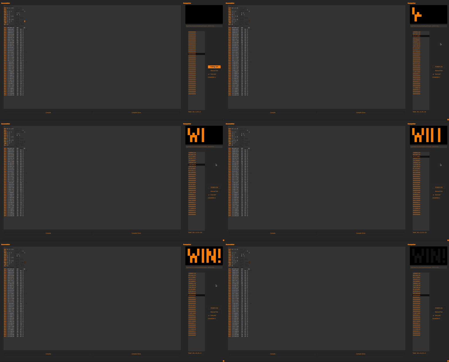
RISC-06 In Action

A simplified win screen renderer!  The code to the left isn't meant to be compiled all at once; just put it in there so it'd be visible.
In that case - perfect time to show it off/talk about it!  The RISC-06 is sort of built around the same fundamental ideas as the TC-06 (e.g, instructions & arguments all get stuffed into one memory address, you have versatile-ish registers, self-modifying code is going to be fairly commonplace), but designed to be even more ridiculously minimal.  Each memory address is 1 byte, the first 3 bits of which are the op-code, and the last 5 of which are arguments.  That means we have 7 main op-codes (8, if you count NIL) - not a whole lot to work with!  Most data is byte-based, too - registers, memory addresses, even the data used for the various peripherals.  The current default setup is 32 bytes of RAM, a 16x8 1-color monitor, a 256-address (the maximum without making one that needs two GETDATA equivalent ops run to read, or three to write!) drive, and at some point, a keyboard.

-=OVERALL INFO=-
 * 32 bytes of RAM.  One byte = one address.
 * All data in bytes.  ALL DATA.  Even the program counter, meaning a hard max of 256 bytes of RAM and drive space.
 * Two 1-byte registers.  Used by MOV, DAT, OPR, BRN, and more - see op-code documentation for specifics.
 * Runs at 30 Hz.
 * First 3 bits are op-code, meaning there are 8 code slots, with 5 bits of argument space.
 * 256-byte "drive" on port 0.  (literal max because byte-based)
   * Run DAT 1 twice to write to it - first to specify the output address, then the data itself.
   * DAT 0 expects its argument to be the requested address, and returns its contents.
 * 2-color 16x8 monitor on port 1.  (1 bit color, 4 bit X, 3 bit Y)
   * DAT 1 expects first a color bit, then the 4 X bits, then the 3 Y bits, and will draw immediately.
   * DAT 0 expects first a 1-bit flag for COMMAND or COLOR.  If flag is 0, it returns the status of the selected pixel, otherwise the full command, then 4 X bits, then 3 Y bits.
 * This is a "reduced instruction"/simplified version of the TC-06 architecture, potentially to be implemented with homebrew IRL hardware.
 * In theory, it is, like the original TC-06, a TURING COMPLETE system.
 * SAMPLE CODE - WRITE BLINKENLIGHTS POSITIONS TO DRIVE, FLASH:
DAT 1 1 0 0  //ADR00
DAT 1 1 0 1  //ADR01
JMP 0 2      //ADR03
DTC 10001001 //ADR04
OPR 6 1      //ADR05
DAT 1 1 0 0  //ADR06
DAT 1 1 0 1  //ADR07
JMP 0 2      //ADR08
DTC 00001001 //ADR09
OPR 6 0      //ADR10-LOOPS
DAT 0 1 1 0  //ADR11
DAT 1 0 1 0  //ADR12
OPR 6 1      //ADR13
DAT 0 1 1 0  //ADR14
DAT 1 0 1 0  //ADR15
JMP 1 6      //ADR16-LOOPE
//RAM[4] & [9] are pixel data.
//4 is 1,1=ON, and 9 is OFF.
//Write them to drive[0,1].
//Loop loads them to Reg1...
//...and draws 'em. -=OP-CODE: NLS (N/A)=-
 * The equivalent to Senbir's NILLIST.
 * NILLIST.
-=OP-CODE: NIL (000)=-
 * Null space.  Skipped past, though it takes a cycle.  Assumed to be empty.
 * NIL.
-=OP-CODE: HLT <5-bit timer> (001)=-
 * If timer==0, halts until reboot.
 * Otherwise, halts for specified number of clock cycles, meaning halts of up to ~1.06 seconds.
 * HLT.
-=OP-CODE: JMP <1-bit flag> <4-bit dest. addr.> (010)=-
 * Jumps the program counter forwards or backwards the specified number of addresses.  Will wrap around RAM if need-be.
 * Flag 0 = forwards
 * Flag 1 = backwards
 * JMP, but localized.
-=OP-CODE: MOV <1-bit flag> <1-bit register> <3-bit addr.> (011)=-
 * If flag is 0, loads something from the first 8 bytes of RAM into register 0/1.
 * If flag is 1, does the opposite, loading from register 0/1 into RAM.
 * If an offset is done with OPR, it adds that to the specified address.
 * MOVI and MOVO combined into one, more limited function.
-=OP-CODE: DAT <1-bit flag> <2-bit peripheral id> <bit argument 1> <bit argument 2> (100)=-
 * If flag is 0, is GETDATA.
   * Argument 1 specifies the return register, either 0 or 1.
   * Argument 2 specifies where to get the command data from, either the opposite register (false), or RAM, 2 addresses ahead (true).
 * If flag is 1, is SETDATA.
   * Argument 1 specifies which register to use, if registers are to be used.
   * Argument 2 specifies where to get the command data from, either the specified register (false), or RAM, 2 addresses ahead (true).
 * GETDATA and SETDATA combined into one, more limited function.
-=OP-CODE: OPR <4-bit op> <1-bit optional flag> (101)=-
 * Operation 0: Addition & Subtraction.
   * Flag 0: Subtraction.  Registers[0] = Registers[0]-Registers[1];
   * Flag 1: Addition.  Registers[0] = Registers[0]+Registers[1];
 * Operation 1: Multiplication & Division.
   * Flag 0: Division.  Registers[0] = Registers[0]/Registers[1];
   * Flag 1: Multiplication.  Registers[0] = Registers[0]*Registers[1];
 * Operation 2: Copy
   * Flag 0: Registers[1] = Registers[0];
   * Flag 1: Registers[0] = Registers[1];
 * Operation 3: Modulo & Exponent
   * Flag 0: Modulo.  Registers[0] = Registers[0]%Registers[1];
   * Flag 1: Exponent.  Registers[0] = Registers[0]^Registers[1];
 * Operation 4: Jump Proper
   * Flag 0: Jump directly to the memory address with ID equal to the contents of register 0.
   * Flag 1: The same, but for register 1.
   * Wraps around if there's an overflow (e.g, if addr 48 is requested when there's only 32 addresses, it goes to addr 16)
 * Operation 5: Offset
   * Flag 0: Sets the current offset to the contents of register 0.
   * Flag 1: Sets the current offset to the current program counter.
   * Like the proper jump, will wrap on overflow in the case of flag 0.
 * Operation 6: Set01[0]
   * Flag 0: Registers[0] = 0;
   * Flag 1: Registers[0] = 1;
 * Operation 7: Set01[1]
   * Flag 0: Registers[1] = 0;
   * Flag 1: Registers[1] = 1;
 * Operation 8: Set23[0]
   * Flag 0: Registers[0] = 2;
   * Flag 1: Registers[0] = 3;
 * Operation 9: Set23[1]
   * Flag 0: Registers[1] = 2;
   * Flag 1: Registers[1] = 3;
 * Operation 10: Shift
   * Flag 0: Shift Registers[0] forwards by the number of bits specified in Registers[1].
   * Flag 1: Shift Registers[1] forwards by the number of bits specified in Registers[0].
 * A mix of MATH and UTL.
-=OP-CODE: BRN <2-bit op> <3-bit dest. addr> (110)=-
 * Operation is either == (0), != (1), 1>2 (2), or 1<2 (3).  Compares registers 1 and 2.
 * Jumps forwards up to 9 addresses (pointer = pointer + 2 + destAddr (0-7)) if the comparison is true.
 * Otherwise, ticks forwards once like normal.
-=OP-CODE: SPC <3-bit start point> <1-bit length (length=(arg+1)*2)> <1-bit offset>=-
 * Splices 2 or 4 bits from register 0 and pastes them into the same position (or the same position+1, wrapping cleanly if need-be) in register 1.
 * A simplified, even more finnicky PMOV.

Despite its limitations, I feel like it's actually more usable than the standard TC-06 assembly.  It seems a bit less reliant on self-modifying code (SPC/"Splice", the PMOV equivalent, and OPR 10, the PMOV offset equivalent, haven't been implemented under the hood yet, and I still wrote that image renderer!), and the register setup feels somehow less overwhelming than Senbir, even though it's far more limited.  I'm loving working with it so far.

Of exciting note, the actual VM for it is written using C++, in such a way that I can hook the simulation function up to Unity down the line and make it work in Senbir.  Getting an ingame RISC-06 computer up and running will be good practice for porting the TC-06 architecture itself to C++ - I've already learned a good bit about compiling it all, linking, dealing with data types, etc.  The visual/UX frontend here is QT-powered, and themes itself depending on your OS theme settings.  I plan to change some of it (at least the Assembler portion) to use some color choosers in the Options menu so it'll look good & be easy to tweak no matter what OS you're running on.


Your RISC-y setup looks good!  I'll admit I'm having a little bit of trouble wrapping my head around parts of it - like immediate-mode numbers in ADD/SUB/etc, how do they work, both on the Assembler level (e.g, would ADD 1 5 jump the pointer forwards five?), and the processor level (how does it decide between using registers & immediate-mode numbers?); the latter is why there's not much of that in Senbir, I couldn't figure out a good way of using immediate-mode numbers without making them an argument (say, a bit), which removes from the number of bits you have available for other arguments.

(I was...a bit one-track-minded about trying to maximize the number of available memory addresses, originally; the max was originally bound by the limitation of MOVI/MOVO, though you can now skirt past that to 2^32 addresses via the power of OFST.  This was especially noticable in the ye-olden TC-06 prototype I shared the gif of a while back - both my rather slipshod attempts to counter the storage issues, and the issues themselves having pretty big numerical impacts.)


Should definitely add an MMU as an optional addition at some point, though I'm not sure if it should be a custom addition to the assembly language itself (e.g, a new op-code for memory management), or a custom device of some sort you ping with GET/SETDATA - they sound way too handy for just about any situation one could imagine not to have around in some form.  ...Hm, maybe an OFST expansion?  Like something you could enable/disable in Custom mode, "MMU OFST" - it would rework the op-code in some shape or form to emulate an MMU.


I understand, now.  Thought there was an undocumented/unintended feature that would enable a monitor that technically uses more than 32 bits, but can function normally via the Extended SETDATA offset feature.

Not too sure what to say about that storage quandry, though.  If I were designing it, I'd probably choose to store emulated monitor commands in some chunk of memory set aside for that purpose, even if it means suffering a performance/storage hit.  Maximum compatibility is important, and as something of a security freak, I'd say that having little VM-specific quirks like that is...dangerous.  Someone looking to write a TC-06 virus (why anyone would is beyond me, but...thinking through these things anyway!) could intentionally check the behavior of that operation to deduce if their program is in a VM or not.  Generally tend to think that providing that sort of info can be a dangerous security hole.

(1 edit)

Aaah, I see, you were going for minimalism rather than RISCyness.

(IIUC (which I'm not really sure about), RISC's "reduced instruction" is not really about having a reduced (as in small) set of instructions, or about each instruction word being reduced (small), but about the instruction itself (as in the operation it performs) being reduced to its essentials (as in not doing more than it has to).

Basically, not doing several operations with one instruction, in terms of what the processor would have to do behind the scenes to complete the instruction - and in particular not optional steps that could be done with other instructions instead. (Hence ending up with things like a load/store architecture.)

I think the underlying idea is that by making each instruction do just one thing, it's much easier to make each instruction execute quickly, so that the processor can instead be made to execute more instructions per second, for a higher total data throughput - thus getting more done, more efficiently (since it takes less hardware to implement).

This doesn't mean that the instructions can't do complicated things (like, say, a step of AES encryption) - just that the instruction for it shouldn't also do other things. IIUC that is.)


Regarding your RISC-06 ISA: I think I like it. It's certainly interesting.

I haven't fully grasped the entire instruction set yet, or how exactly to do much with it (like your win screen), but that would probably come with actually attempting to write something in it. At first glance I would think that having only two registers would be severely limiting, but I guess some of the instructions being able to instead directly use memory alleviates that (also some useful values being quickly available via specific instructions).

Also, numbers never going above 255 probably makes them easier to reason about. Besides, limitations can be inspiring, which might be another reason it seems easier.

One thing I might suggest, though, to make it easier to work with, would be to consider acknowledging that it doesn't really have fixed-width (3-bit) opcodes - instead, it has variable-width opcodes (I've seen ones I would consider to have 3 (HLT), 4 (MOV 0), 5 (BRN 0), 7 (OPR 4), and 8 (OPR 0 0) bits) - and setting up/naming assembly instructions accordingly to represent the operation and to simplify the arguments.


Re: the C++ VM implementation: nice! Well done. Good luck adding the rest! :) (I haven't done C++ myself.)


Re: reg+imm: well, I'll try to explain it in detail, but the short answer is that all the parameters are required, and the processor actually doesn't decide between registers and immediate-mode, it always uses both (and thus always does the same thing for that instruction).

I think an example might help; let's go with MUL for now, the others work equivalently.

1000: MUL    reg4 reg4 reg4 imm16          // MUL dst src1 src2 val
                                             // dst = src1 * (src2 + val)

The first column is the opcode for the instruction, here 1000, followed by the name that is used for it in assembly code, here MUL.

The rest of the line, up to the // comment, describes the type and bit width of the parameters to this instruction. There are three distinct types:

- reg : register, these bits name a register to be used for this parameter
- imm : immediate, these bits constitute an immediate value that is used as-is
- zero : zeroes, these bits should be zero (only used in NOP; maybe ign (for ignore) would be better? I'm not sure)

In other words, this instruction has 4 parameters, the first three are 4 bits wide each and refer to registers, while the last is 16 bits wide and is an immediate value.

The comment on the first line shows the assembly instruction with its parameters again, but this time shows the names of the parameters instead of their types. They are in the same order as the first time, which is also the order they would be specified in when using the instruction in assembly code. (I haven't yet 100% decided upon the field ordering inside the binary instruction word.)

So, the first parameter is named "dst" and refers to a register. The next two are named "src1" and "src2" respectively, and also refer to registers. The last one is named "val" and is a 16-bit immediate value.

The second comment line (slightly indented) shows the operation performed by this instruction, in a higher-level language pseudo-code.

Translating to prose, this means that MUL sets the dst (destination) register to the result of multiplying the src1 (source) register with the sum of the src2 register and the val immediate value.

In short, this is an add-and-multiply instruction - a concept I'm pretty sure I've stolen from somewhere, though I can't remember quite from where exactly.

In assembly code, it would look something like this:

MUL 2 3 4 10

which would take the value of register 4, add 10 to it, multiply the result with the value of register 3, and store the result of that in register 2: R2 = R3 * (R4 + 10)

As noted under the instruction list, most of the immediate values can be negative, so this is also a valid instruction:

MUL 2 2 0 -1

which would do R2 = R2 * (R0 - 1) = R2 * -1 and thus negate R2 (since R0 is always 0).


ADD similarly requires 4 arguments (so "ADD 1 5" is not actually valid code), and works equivalently - add val to src2, then add that to src1, then save the result in dst.

So, to move the program counter forward by 5 (to skip the next 5 instructions), you could do this:

ADD 1 1 0 5

which works because R0 is always 0, so it becomes R1 = R1 + (0 + 5) = R1 + 5

Worth noting at this point is that R1 starts out pointing at the address immediately after the ADD instruction, which is why this skips 5 instructions, instead of skipping 4 and running the 5th. Adding 0 is thus a no-op.

(This also means that moving backwards requires higher numbers than moving forwards - subtracting 0 is also a no-op, subtracting 1 is an infinite loop, and subtracting 2 jumps back to the instruction immediately before the current one. (If I had an explicit instruction for relative jumps, it might work differently, but setting R1 is essentially manipulating the internal state of the CPU directly, so no such niceties here.))


To be honest, I expect that most uses of the arithmetic instructions will have a zero in one of the two last arguments, depending on whether it wants to use a register value or an immediate value, but the CPU doesn't care - it always does the same thing: adding them together before applying the main operation.


Re: MMU, I agree that having one would probably be very nice, but you may want to take a look at how they typically work before you make too many plans about how to emulate one.

The details differ between MMU models, but from what I've seen (which admittedly isn't much), they typically require you to set up some data structures in main memory (to define the memory mapping(s)), usually with some specific alignment (for speed reasons), and then you have to tell the MMU where that data structure is, and enable it. Sometimes there are other settings too, like ways to enable/disable parts of the mapping for fast context switching, but that's model-specific.

Another thing the MMU needs is some way to call the kernel when a page fault happens, including a way to tell it which address caused the fault, and unlike most platforms the TC-06 doesn't have any standard calling conventions (e.g. for interrupts) to rely on for that. I guess we'd need a way to store the fault handler address at minimum, and maybe some other things for various details.

I suppose you could make the offset register (what OFST manipulates) instead be a pointer to that MMU data structure, which enables the MMU when set. But that would completely break backwards compatibility with older programs that already use OFST (like your kernel), since it would suddenly work completely differently and trying to use it in the old way would probably make the system crash (since the MMU would suddenly be pointed at garbage data). Changing the way the OFST instruction itself works (parameters etc.) would cause similar issues.

Unless you don't care about BC breaks, I'd say a new opcode would be a better idea than overriding OFST, as at least it wouldn't have those BC issues - well, unless and until you change how the MMU works in such a way that that instruction would have to change as well, but it might be possible to plan for at least some of that.

I've been thinking that the device API (GETDATA/SETDATA) would be nicer for this, because it already has addressing we could use for multiple "registers" for those various pieces of required data, and it's sort of built in to the device concept that a device might not be present or has been replaced with a different one. That's just my thinking though, you might feel differently about it.

I had another idea for at least part of the problem, though - namely that most of those values could probably be stored in memory, linked to the mapping data structure we point the MMU to. Then those mappings could be set up to protect those settings (along with the mappings themselves) so that any user programs can't mess with them, only the kernel can. This may cause some wasted memory if the alignment doesn't match up perfectly, though. Also, that still leaves the initial pointer to that data structure without a safe place to live, so we'd still need one of the other solutions for that - and then we might as well use that solution for the rest, too.

On the other hand, if the MMU can protect memory, it can probably protect its own registers as well, and simply ignore any disallowed SETDATA calls (or complain to the kernel about it).

An interesting point from a security point of view is that the user program shouldn't be able to change the mappings, but the kernel should, so then we somehow need to transition from user mode privileges to kernel mode privileges without letting the user mode program switch the mode on its own (privilege escalation), despite it being in control of the CPU... Luckily there's a fairly simple solution, if the MMU has the right feature. (Namely having it switch mappings automatically right before calling the kernel's page fault handler. Then the mode switch happens by triggering a page fault, which the user mode program cannot do without transferring control to the kernel.)

Of course, none of that really matters if we don't think this kind of security is necessary in Senbir. If we assume that programs are never malicious and are always well-behaved (won't try to mess with the MMU), then we don't really need to protect it. (I'd prefer not to assume that, though.)


Re: the storage quandary: yeah, personally I'd probably do the safe and slow thing too, for much the same reasons. Many others wouldn't, though, whether because they didn't think of it or because they cared more about performance... Lots of examples of that. On the other hand, though, I suppose most of those people would never play Senbir to such a depth that it mattered anyway...