
it's a feature that is activated in the Code, if your familiar with Unity Development their is an Object called "VideoFeatures", or something, and you can activate that to get the experimental features like seeing the Displays in a chip. Their are some mods, And very helpful posts on how to do this on this forum, so if you can find those you should be able to activate this feature.
A member registered Nov 07, 2022 · View creator page →
Recent community posts
In My last post I made a 16-Byte RAM chip.
Today I'm making an ALU, an Arithmetic and Logic Unit.
Here's how:
The ALU:
-----------------------------------------------------------
Architecture:
The ALU has 8 Functions on it, 4 Logical, 4 Arithmetic.
Logical: NOT, OR, AND, XOR.
Arithmetic: ADD, SUB, INC, DEC.
-----------------------------------------------------------
The Addition and Subtraction:
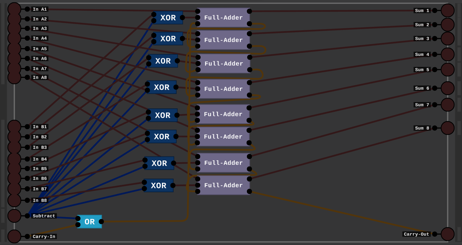
This Chip has 2 8-bit inputs, and an 8-bit Output along with an extra 9th bit for output.
And a Carry Input, and a Subtraction Signal. When the Subtraction Signal is on we use 2s Complement
to Subtract the 2 inputs.
Note:
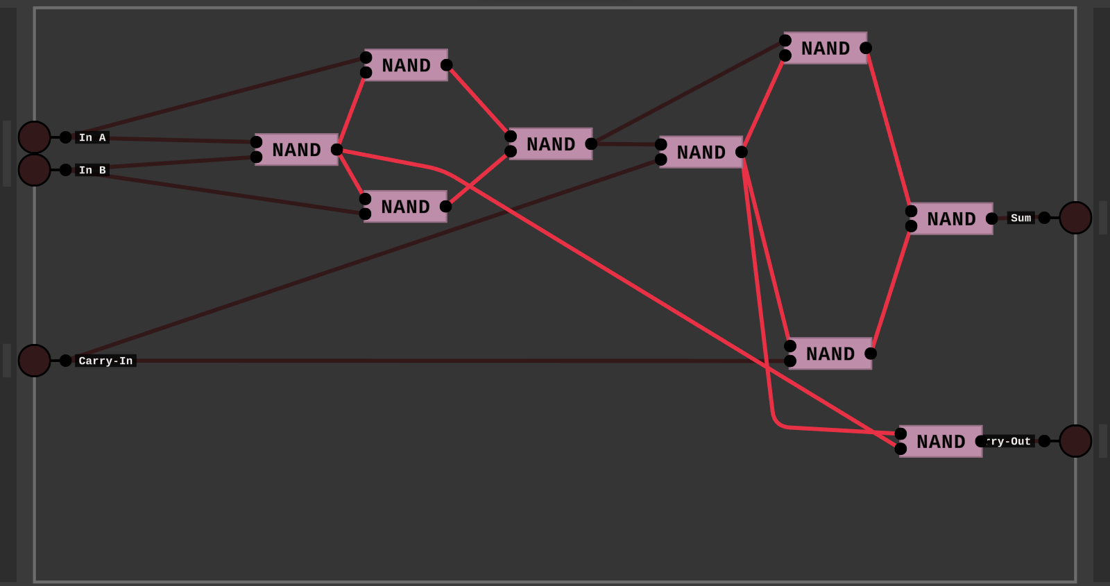
This is the Full-Adder chip, the design is umm, pretty bad, but it works!
-----------------------------------------------------------
The Logical Part:
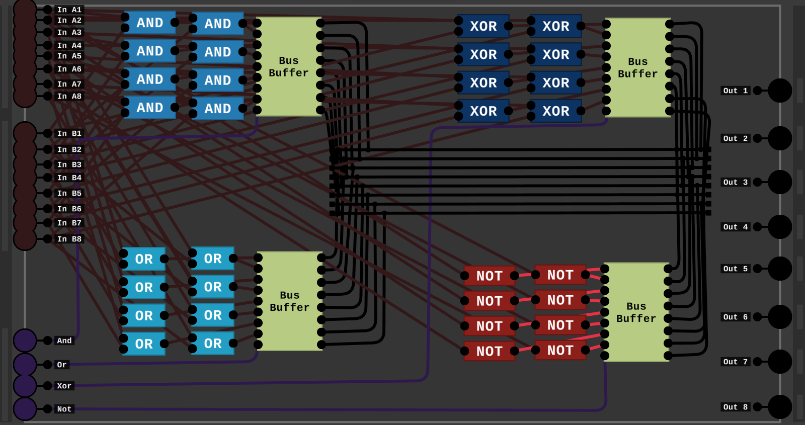
So this does the Logical Operations.
It has 2 8-bit inputs, and 4 selection signals.
Depending on which selection is on, the output of that operation is put on to an 8-Bit Bus wire and fed out of the chip
on an 8-bit output number.
-----------------------------------------------------------
The finished Build:
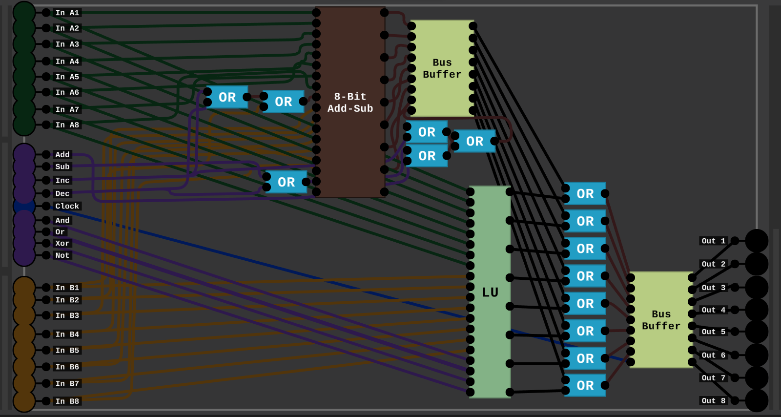
Finally, We combine everything together to make a ALU.
First the Arithmetic part, we have the 4 selection signals, and when the In B1 Signal or the Decrement/Increment signal is on then the first bit of the second number is on. And the Subtraction on the chip is on, when the Decrement or the Subtraction signal is on.
Logic is just the LU chip, the Arithmetic and Logic are put through an OR gate so we can choose which to output, and we also have the Clock.
It ahh, I didn't setup the Clock properly, so I might address that in the future and add some stuff to the ALU, but that's it for now.
-----------------------------------------------------------
Thanks for reading.
16-Byte RAM:
-----------------------------------------------------------------------------------------------------------------
So I saw that people were talking about making computer RAM in the posts.
And I thought I could probably build this.
So I made a 16-Byte Ram Chip:
--------------------------------------------------------------------------------------------------------------------------------------------------------------------------------
Step 1: The 1-Byte Ram:
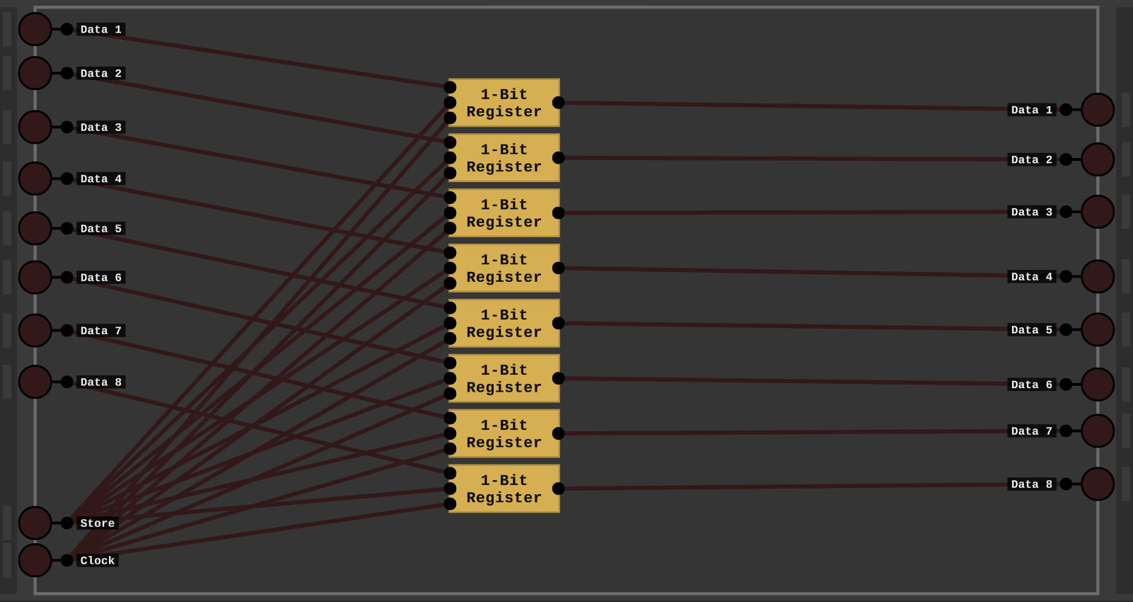
So first I put together 8-1-Bit-Registers to make a 1-Byte Ram Chip.
--------------------------------------------------------------------------------------------------------------------------------------------------------------------------------
Step 2: The 4-Byte Ram:
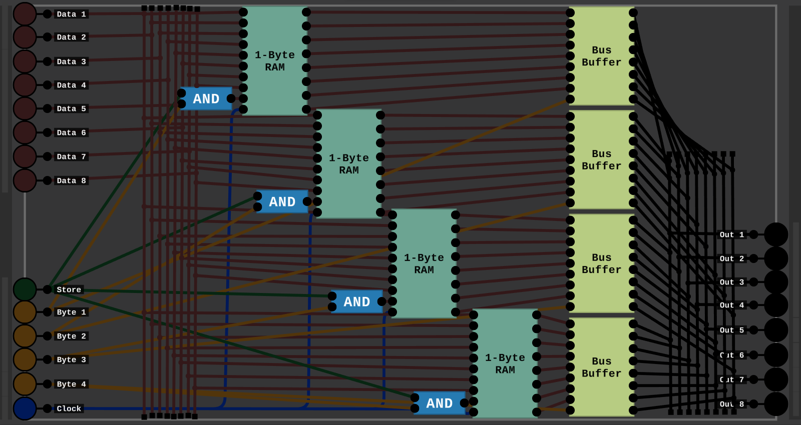
So This may look like a mess of wires, but I'll try and explain.
Pins:
So there's 8 Data In Pins, The Store And Clock Pins. Then 4 Pins for selecting which Byte to write to.
Wiring:
Then Each 1-Byte Chip gets its own Byte Pin, Then I use some Ands to store in that Byte If the Store Pin and that Bytes Pin is on.
Then I store the Data In Pins in that Byte of RAM. Then Everything goes into a Tri-State Buffer. Which the Byte Pins are used to turn the Buffers On and Off. Then the Output of the Bus Buffers are feed to the Data Output Pins.
--------------------------------------------------------------------------------------------------------------------------------------------------------------------------------
Step 3: 4-16 Binary:
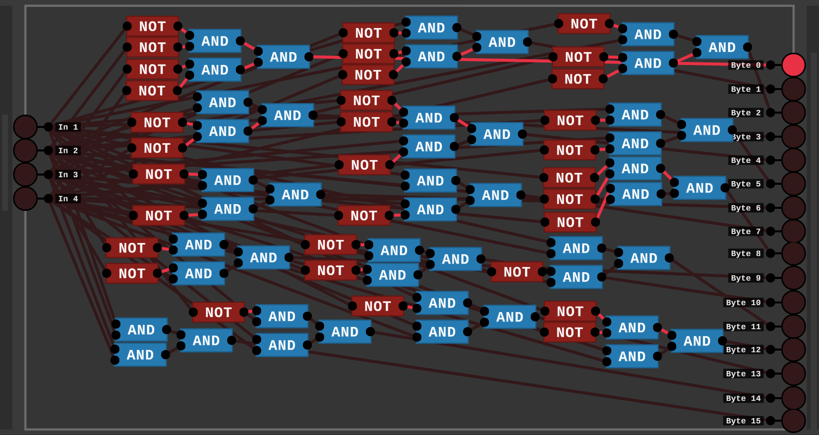
So Here there's 4 Inputs and 16 Outputs. For each combination of the 4 Inputs there's an Output Pin. So using the 4 Inputs we can select between 16 different Bytes of Memory.
--------------------------------------------------------------------------------------------------------------------------------------------------------------------------------
Step 4: 16-Byte RAM:
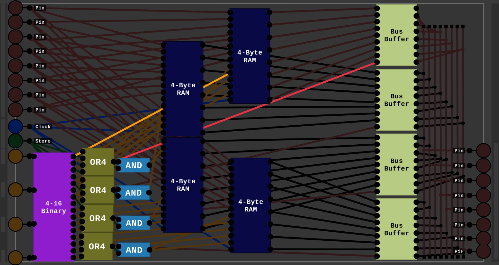
So this is basically a bigger version of the 4-Byte RAM. But everything is scaled up for 16-Bytes.
We also use the 4-16 Binary to select between all 16 Bytes of Ram. And like before feed there outputs through Tri-State Buffers.
And for the Store signal I turn the 16 Byte Selection signals back down to a 4 Byte signal to store if that 4-Byte Ram's Byte Signal is on.
Then use the full 16 Byte Selection Signals to pick between which Byte in the 4-Byte Chip to store in.
And ALL of this uses a Clock, so it could be used in a computer.
--------------------------------------------------------------------------------------------------------------------------------------------------------------------------------
Wow, you actually read all of this? Thanks.
-TheXadGaming